


– 5 –
ASSEMBLING THE OVEN TO THE STAND
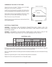
Unpack the oven and stand. Position oven on its back,
taking care not to scratch or damage it.
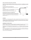
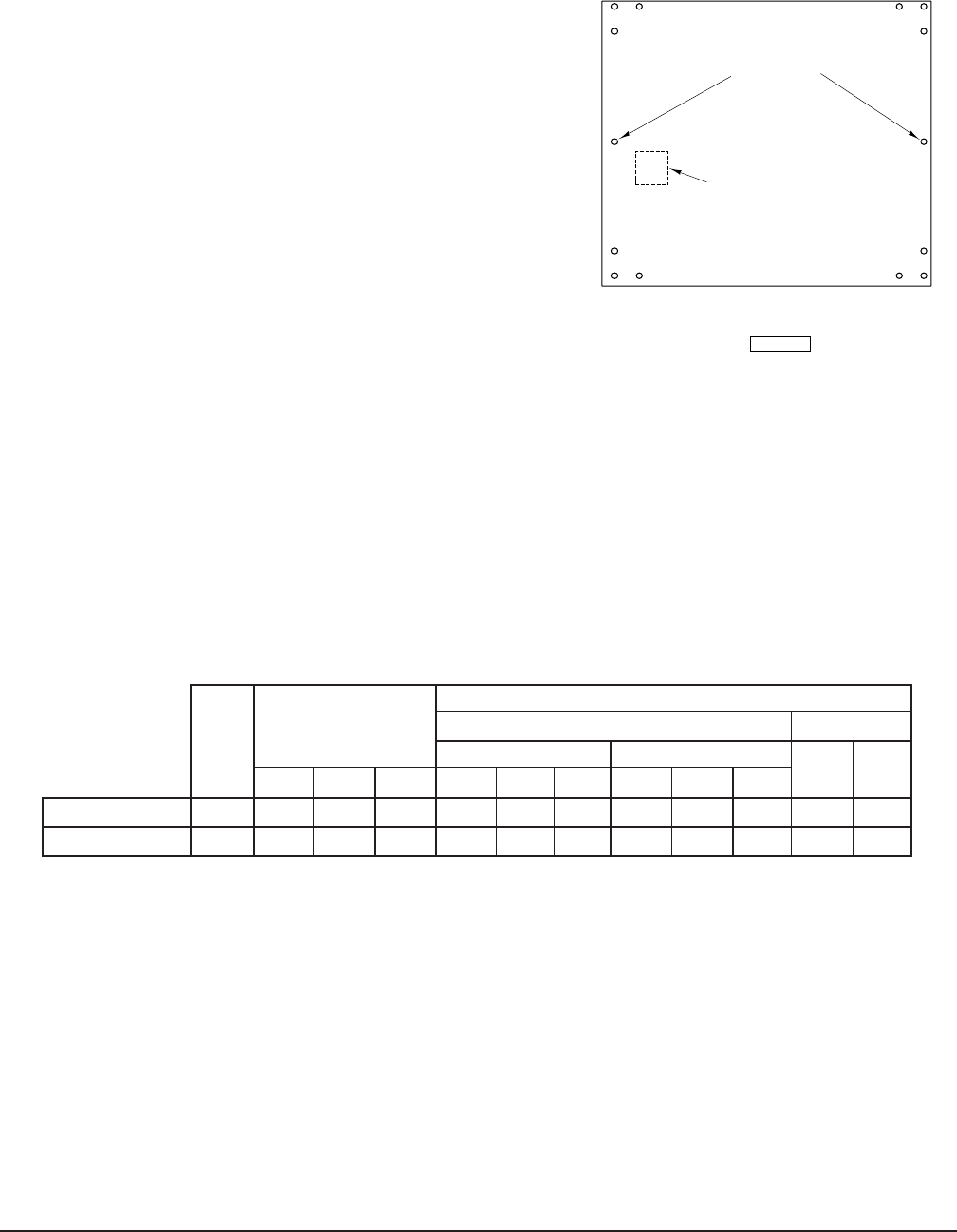
Install the two locating studs (included in the stand carton)
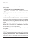
into the screw plates on the underside of the oven ( Fig. 2).
Attach each of the four leg assemblies to the bottom of the
stand with the 24 bolts and lockwashers (6 per leg).
Mount the oven on top of the stand.
Adjust the legs to ensure that the oven racks are level in the
final installed position.
ELECTRICAL CONNECTIONS
WARNING: ELECTRICAL AND GROUNDING CONNECTIONS MUST COMPLY WITH THE
APPLICABLE PORTIONS OF THE NATIONAL ELECTRICAL CODE AND/OR OTHER LOCAL
ELECTRICAL CODES.
WARNING: DISCONNECT THE ELECTRICAL POWER SUPPLY AND PLACE A TAG AT THE
DISCONNECT SWITCH INDICATING THAT YOU ARE WORKING ON THE CIRCUIT.
ELECTRICAL DATA
NOMINAL AMPS PER LINE WIRE
TOTAL
3-PHASE LOADING
3 PHASE 1 PHASE
KW
(KW PER PHASE)
208V. 240V.
L1-L2 L2-L3 L1-L3 L1 L2 L3 L1 L2 L3
208V. 240V.
Single Oven 5.5 2.5 0 3.0 23.0 10.0 12.0 20.0 9.0 11.0 26.0 23.0
Stacked Ovens 11.0 5.0 0 6.0 46.0 20.0 24.0 40.0 18.0 22.0 52.0 46.0
Knockouts are provided on the back and bottom of the oven for making conduit connections. Remove
the screws from the front control panel for access to the terminal block.
Wire and required hardware for making connections between stacked ovens are furnished with the leg
stack set.
Replace the right side panel if it was removed during electrical connection.
Replace the front control panel and turn on the power supply.
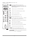
Fig. 2
REAR OF TOP OVEN
KNOCK OUT WELDED PLATE
FOR FLUE EXTENSION INSTALLATION
BOTTOM
LOCATING STUDS
PL-52992
FRONT OF TOP OVEN