


– 5 –
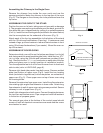
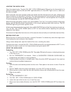
Assembling the Chimney to the Single Oven
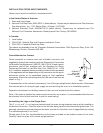
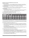
Remove the chimney from inside the oven cavity and use the
screws provided to fasten the chimney to the top rear of the oven
(Fig. 2). The flanges on the chimney are to be positioned over the
top cover.
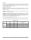
ASSEMBLING THE OVEN TO THE STAND
Position the oven on its back, taking care not to scratch or damage
it. The gas pipe connection protrudes beyond the back; provide for
this when the oven is tipped back by resting it on suitable spacers
(2 x 4's). Install the two locating studs (included in the stand carton)
into the screw plates on the underside of the oven (Fig. 3).
Attach each of the four leg assemblies to the bottom of the stand
with the 12 bolts and lockwashers (3 per leg). If casters are used
instead of legs, put fixed casters in rear and swivel casters in front
using 12 bolts and lockwashers (3 per caster). Mount the oven on
top of the stand.
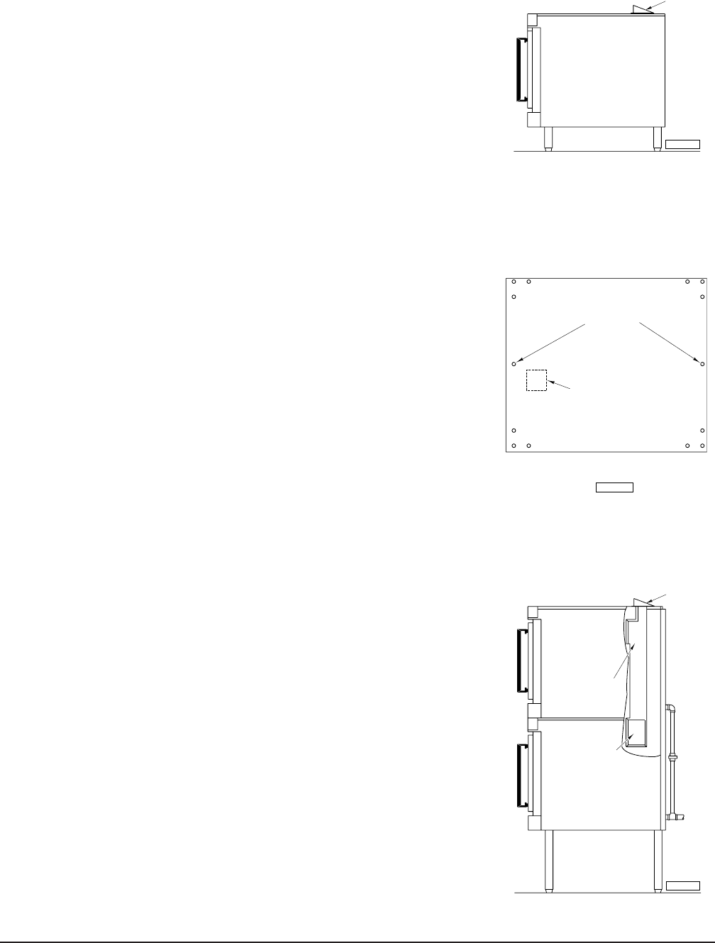
ASSEMBLING STACKED OVENS
Determine which oven will be on the bottom and place it on its left
side, being careful to avoid scratching the finish. Install the four 16
3
/4"
(42.5 cm) legs, using the 24 bolts and lockwashers provided (6 per
leg). Remove the two
7
/16" (1.1 cm) knockouts on each side of the top
cover and place oven in upright position at installation location.
Turn the adjustable feet in or out to level the oven front-to-back and
side-to-side (refer to LEVELING, page 6).
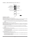
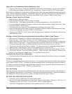
Remove right-hand side panels from both ovens. Remove welded
plate from bottom of upper oven (Fig.3). Install the two locating
studs (included in leg stack set) into screw plates on underside of
upper oven (Fig. 3). Place upper oven on top of lower oven using
the locating studs.
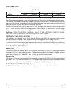
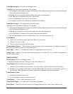
Remove flue extension from upper oven. Install long flue extension
into existing right-angled flue extension in lower oven. Attach long
flue extension to wall of upper oven using screws provided. Secure
chimney to roof of upper oven (Fig. 4).
Install right side panels on both ovens. Connect the piping between
the top oven and bottom oven. Pipe compound must be resistant
to the action of propane gases.
The manual gas valve at the bottom of the control panel should
remain off until all electrical connections are made and the ovens
are checked or used.
CHIMNEY
PL-52240
Fig. 2
RIGHT ANGLED
FLUE EXTENSION
LONG FLUE
EXTENSION
CHIMNEY
PL-52221
Fig. 4
REAR OF TOP OVEN
KNOCK OUT WELDED PLATE
FOR FLUE EXTENSION INSTALLATION
BOTTOM
LOCATING STUDS
PL-52992
FRONT OF TOP OVEN
Fig. 3