– 2 –
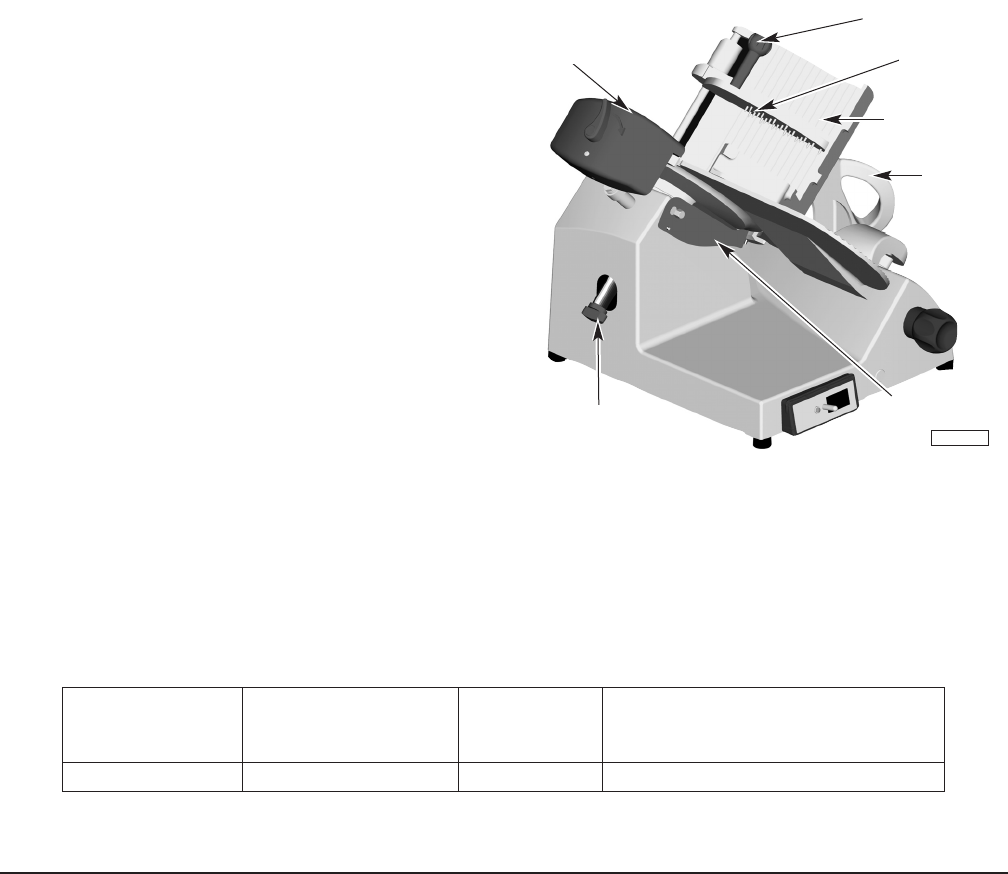
MEAT GRIP
MEA
T GRIP HANDLE
SHARPENER
CARRIAGE TRAY
CARRIAGE
HANDLE
PL-41551-1
KNIFE COVER KNOB
DEFLECT
OR
Installation, Operation and Care of
EDGE SLICER
SAVE THESE INSTRUCTIONS
GENERAL
The Edge slicer is equipped with a
1
⁄
3
HP motor. A cord and plug is furnished as standard equipment.
The slicer knife is chrome-plated forged carbon steel. The slicer base, carriage tray support arm,
knife cover, ring guard and gauge plate are made of smooth-finish anodized cast aluminum for easy
cleaning. The rear-mounted meat grip is hinged on the rod behind the carriage tray. The top-mounted
knife sharpener is removable for cleaning.
The Edge slicer must be thoroughly cleaned and sanitized after installation and before being used.
Refer to Cleaning, page 3.
INSTALLATION
UNPACKING
Immediately after unpacking the slicer, check for
possible shipping damage. If the slicer is found to
be damaged, save the packaging material and
contact the carrier within 15 days of delivery.
Prior to installing the slicer, test the electrical service
to make sure that it agrees with the specifications
on the machine data plate. The data plate is located
on the right side of the slicer base.
The CARRIAGE TRAY SUPPORT ARM is secured to the
slicer by turning the K
NOB below the SUPPORT ARM
clockwise until snug (Fig. 2).
Mount the SHARPENER on top of the slicer (Fig. 1)
by lowering it onto its post. The S
HARPENER can be
removed for cleaning.
The DEFLECTOR (Fig. 1) should already be mounted
below the knife.
ELECTRICAL
WARNING
: THIS MACHINE IS PROVIDED WITH A THREE-PRONG GROUNDING PLUG. THE
OUTLET TO WHICH THIS PLUG IS CONNECTED MUST BE PROPERLY GROUNDED. IF THE
RECEPTACLE IS NOT THE PROPER GROUNDING TYPE, CONTACT AN ELECTRICIAN.
ELECTRICAL DATA
Model Volts / Hertz / Phase Machine Amps
Minimum Circuit Ampacity
Maximum Protective Device
AMPS
EDGE 120 / 60 / 1 3.5 15
Compiled in accordance with the National Electrical Code, NFPA 70, latest edition.
© HOBART CORPORATION, 2002
Fig. 1


