


-4-
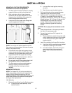
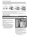
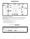
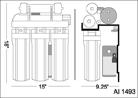
DIMENSIONS OF SYSTEM SHOWN
INSTALLATION
MOUNTING LOCATION REQUIREMENTS
CAUTION: Do not mount to equipment.
1. The filter system must be mounted on a sturdy
support structure or wall and must be level.
2. Allow a minimum of ten inches clearance
around the left and right sides and 14 inches
clearance from the bottom of the system for
routine maintenance and servicing.
3. Locate the RO filter system and storage tank
near the equipment it services.
NOTE: The shorter the distance between the RO
filter system and the equipment, the lower the water
delivery line pressure drop.
4. Ensure there is an open drain nearby to drain
waste water produced by the RO system. Most
commonly this is the same drain used by the
equipment the RO filter system is servicing.
5. Make sure 120V electrical service is within six
feet of the RO mounting location.
6. Do not install the RO filter system where it will
be exposed to hot air or steam exhaust.
7. The filter system must be protected against
freezing. Failure to do so could result in
breakage of the filter housing and water
leakage.
MOUNTING THE RO-150
NOTE: The Hobart RO-150 can be mounted on a
wall or other stable surface that will support its wet
weight of 30 lbs. When mounted to a wall, the
mounting hardware used must be able support its full
weight and withstand the additional forces applied
during pre-filter replacement.
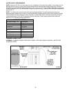
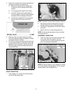
Wall Mounting
1. Remove the pre-filters from the filtration system.
A. Lift the pre-filter head assembly to the
desired location.
B. Level pre-filter head against mounting
structure.
C. Mark the two mounting hole locations.
2. Drill mounting holes to the required diameter
(depends on wall anchors being used).
3. Install two 3/16" mounting screws at least 1-1/4"
in length in the marked locations using the
appropriate wall anchors. Screw in the mounting
screws leaving a 1/8"-1/4" gap. Lift the pre-filter
head assembly and install over mounting
screws. Slide pre-filter head assembly into
place then securely tighten the mounting
screws.
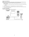
CAUTION: Do not plug in the transformer at this
time.
4. Place the transformer in the space provided to
the right of the permeate pump.
5. Connect the transformer 24V output to the
wiring harness.
A. Route transformer output wiring under right
side of bracket and connect to plug located
on the left side of filter system near high
pressure switch.
6. Insert filter cartridge into the pre-filter housings.
A. Verify that the filter cartridge being installed
matches the labeling on the bracket.
B. For each pre-filter, ensure the O-ring is in
place on pre-filter housing and hand
tighten filter housing onto the pre-filter
head.