


– 3 –
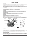
PL-41408-1
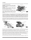
SHARPENER
DEFLECTOR
TOP KNIFE COVER
CARRIAGE TRAY
CARRIAGE TRAY /
SUPPORT ARM
FENCE
INSTALLATION
UNPACKING
Immediately after unpacking the slicer, check for possible shipping damage. If the slicer is found to be
damaged, save the packaging material and contact the carrier within 15 days of delivery.
Prior to installing the slicer, test the electrical service to assure it agrees with the specifications on the
machine data plate. The data plate is located on the right side of the slicer base.
CARRIAGE TRAY
The Carriage Tray is secured to the slicer when the knob on the Carriage Tray / Support Arm is turned
clockwise until snug (Fig. 1). Refer to page 7 for assembly information.
SHARPENER
The Sharpener should already be mounted on top of the slicer and locked to its bracket (Fig. 1).
TOP KNIFE COVER
The Top Knife Cover should already be in place and secured with its Latch Knob (Fig. 1).
DEFLECTOR
The Deflector should already be mounted below the knife (Fig. 1).
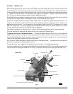
FENCE (Low and High Fences are used with front-mounted meat grip only.)
Either Fence (Fig. 1) can be clamped on the Carriage Tray to limit product movement during slicing.
Model 2812
Fig. 1
ELECTRICAL
WARNING: THIS MACHINE IS PROVIDED WITH A THREE-PRONG GROUNDING PLUG. THE
OUTLET TO WHICH THIS PLUG IS CONNECTED MUST BE PROPERLY GROUNDED. IF THE
RECEPTACLE IS NOT THE PROPER GROUNDING TYPE, CONTACT AN ELECTRICIAN.
CLEAN BEFORE USING
The 2812 or 2912 slicer must be thoroughly cleaned and sanitized after installation and before being
used. Refer to Cleaning, page 6.
1. Back out Thumb Screw.
Lay Fence on Carriage Tray.
2. Rotate to Vertical.
3. Slide Fence Up. Tighten Screw.