


W7340, W7345 COMMUNICATING ECONOMIZER LOGIC MODULES
63-2569—04 4
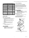
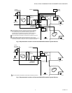
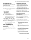
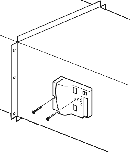
Fig. 3. Mounting to a Duct or Panel.
Enthalpy Sensor (W7340 only)
To measure enthalpy, the logic module accepts signals from
either:
— C7600C Humidity and 10K NTC temperature sensors.
— or a C7400 Enthalpy Sensor.
IMPORTANT
• When using C7400 Enthalpy Sensors, connect the
enthalpy sensors to the humidity sensor terminals;
leave the temperature sensor terminals empty.
• Use C7400A sensor with W7340A or W7340B.
• Use C7400C sensor with W7340C.
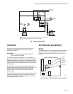
OUTDOOR AIR SENSING
1. Mount each sensor in any orientation that exposes it to
freely circulating air and protects it from rain, snow, and
direct sunlight.
2. Connect it to the logic module.
RETURN AIR SENSING
1. For differential enthalpy or temperature control mount a
second sensor in the return air duct.
2. Connect it to the logic module.
Demand Control Ventilation (DCV) Sensor Input
(W7340 only)
The DCV sensor can be any sensor that provides a 0-10 Vdc
output over a range of 0 to 2000 ppm of CO
2
. The DCV signal
modulates the outdoor damper to provide ventilation based on
occupancy. Mount the sensor according to the manufacturer
specifications. If not available, mount the sensor in an area
with unobstructed air circulation.
IMPORTANT
• Ensure proper polarity of sensor connections.
Incorrect polarity negates the sensor signal.
W7340B: The W7340B DCV economizer logic modules
incorporate a minimum position setting that defaults to 20%,
but can be overridden using the Modbus communication link.
The W7340B DCV maximum position sets the damper position
to a position that the damper goes to if the CO
2
sensor fails. If
the minimum position set point is higher than the DCV
maximum position, on sensor failure, the damper goes to the
higher of the two DCV maximum and minimum position setting.
There is no limit on the damper position on a call from the CO
2
sensor (DCV); the damper can go 100% open.
W7340C: The W7340C DCV economizer logic module has the
ability to set DCV minimum damper position and minimum
position. The DCV minimum position is set to ventilate the
building contaminants and the minimum position is set to
ventilate for the building contaminants and the building
occupants. The installer sets the damper DCV minimum
position and the minimum position based on the design
occupancy and CFM of outdoor air requirements for the space.
The damper will modulate open between the DCV minimum
damper position and the minimum position based on input
from a CO
2
sensor. The damper will not drive 100% open on a
call for ventilation, but can drive 100% open on a call for
cooling. If the CO
2
sensor fails the damper will drive to the
minimum position ventilating for building contaminants and
the building occupants. If the DCV minimum position has not
been set using the following procedure, the default setting will
be 50% of the minimum position setting.
DCV Min and Min Position Damper Set Up
Set up instructions for W7340C DCV damper positions:
1. Remove RAT sensor from RAT terminals.
2. Connect CO
2
sensor to DCV terminals.
3. Apply power to economizer logic module.
4. Wait 10 to 15 seconds for the CO2 sensor to initialize.
Short RAT terminals.
5. Remove CO
2
sensor from DCV terminals.
6. DCV LED will blink 2 times. If LED does not blink, cut
power to economizer logic and repeat steps 1-5.
7. Set DCV minimum position using MIN POS/DCV MIN
potentiometer.
8. Remove RAT short.
9. DCV minimum position is saved to memory and DCV
LED blinks 5 times.
10. Turn off power to economizer logic module.
11. Connect RAT sensor.
12. Turn power on to economizer logic module.
13. Set minimum position using MIN POS/DCV MIN
potentiometer.
IMPORTANT
Steps 3-8 must be completed within 3 minutes after
power up otherwise the configuration process will be
terminated, no changes will be saved and you will
need to repeat steps 1-13.
M17638