


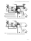
W7340, W7345 COMMUNICATING ECONOMIZER LOGIC MODULES
63-2569—04 8
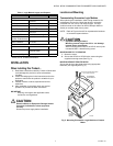
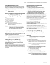
W7340
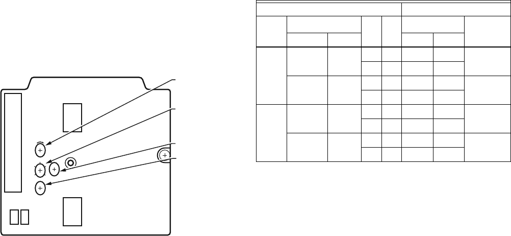
Potentiometers with screwdriver adjustment slots, located on
the face of the device, provide adjustments for several
parameters (See Fig. 9 for locations on device):
— DCV minimum and minimum damper position.
— Enthalpy changeover.
— DCV setpoint.
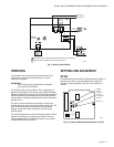
Fig. 9. Location of W7340 potentiometers and LED.
IMPORTANT
Before powering the device read the following Enthalpy
changeover setpoint guidelines:
1. Using the Enthalpy changeover setpoint, the setpoint
can be adjusted until three minutes after powering the
device. until three minutes after powering the device.
2. Through the Modbus, the Enthalpy changeover
setpoint can be modified at any time.
3. If the Enthalpy changeover potentiometer is changed
after the three minute power-up time, no change to
the Enthalpy changeover setpoint will occur unless
power is removed from the device then reapplied.
NOTES:
— The DCV setpoint can be changed at anytime by
adjusting the pot.
— For Enthalpy changeover setpoint see comments
above.
— MIN POS can be changed anytime by adjusting
the pot.
— DCV Min can be changed by procedure on page 4.
Demand Control Ventilation (DCV) Setpoint
The logic module modulates the outdoor damper to provide
ventilation based on the 2-10 Vdc DCV sensor. With no cooling
signal, DCV overrides the DCV minimum damper position
when ventilation requires outdoor air.
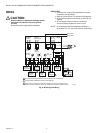
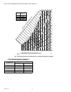
Table 2. W7340 Economizer I/O Logic.
a
For single enthalpy control, the module compares outdoor
enthalpy to the ABCDE setpoint.
b
If both stages of cooling are off, the system is off and the
damper is:
• At DCV minimum position if DCV is below setpoint.
• Modulating if DCV is above setpoint.
c
Modulation based on mixed air sensor signal, modulating
between DCV minimum position and 100% open.
d
Modulation based on DCV signal, limited by minimum
position.
e
Modulation based on the greater of the DCV and mixed air
sensor signals.
Adjusting Minimum Damper Position
The minimum position potentiometer maintains the minimum
outdoor air flow into the building during occupied period.
NOTE: If the mixed air temperature drops to 45° F (7° C), the
mixed air sensor overrides the DCV sensor and
closes the damper to DCV minimum position to
protect the hot or chilled water coils from freezing.
When the mixed air temperature rises to 48° F (9° C),
control reverts to normal operation.
For detailed assistance in minimum position selection,
reference the Economizer Application Guide (form 63-8594)
Ventilation section. The following provides basic guidelines for
minimum position selection and adjustment:
IMPORTANT
1. Adjust the minimum position potentiometer to allow
the amount of outdoor air, as required by local codes,
to enter the building for building contaminants and the
maximum building occupants.
2. This procedure requires use of a quality thermometer
capable of reading to 0.5° F (0.-17.5° C).
NOTE: Make minimum position adjustments with at least a
10° F (-12° C) temperature difference between
outdoor and return air.
See section on DCV setpoint set up on page 4.
PP1
+
-
+
-
ExF
MAT
OAH
OAT
RAT
RAH
DCV
2-10 VDC
DAMPER
POSITION
2-10 VDC
DAMPER
POSITION
OVERRIDE
MIN POS/
DCV MIN
OPEN
DCV
SETPOINT
1500500
STATUS LED
DEMAND
CONTROL
VENTILATION
SETPOINT
ENTHALPY
CHANGEOVER
SETPOINT
MIN POS/DCV
MIN DAMPER
POSITION
M23878
MBUS-
MBUS+
TR1 24V COM
TR 24V AC
C
B
E
A
D
+
_
+
_
INPUTS OUTPUTS
DCV
Enthalpy
a
Y1
b
Y2
b
Compressor
DamperOutdoor Return Stage 1 Stage 2
Below
set
High Low On On On On Minimum
position
On Off On Off
Low High On On On Off
Modulating
c
On Off Off Off
Above
set
High Low On On On On
Modulating
d
On Off On Off
Low High On On On Off
Modulating
e
On Off Off Off