


Y8150 FRESH AIR VENTILATION SYSTEM, W8150 FRESH AIR VENTILATION CONTROL
68-0282—07 4
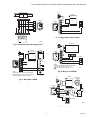
INSTALLATION
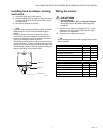
A fresh air duct and damper must be installed between the
outdoors and the return side of the HVAC equipment. The
W8150 control will be mounted near the HVAC system and
wired between the thermostat and the fan control.
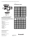
You will need…
• W8150 Fresh Air Ventilation Control.
• damper.
• transformer.
• insulated ductwork.
• outdoor weather hood.
• starting collar.
• access to 120 Vac power.
• airflow measuring tool.
TIPS:
• To meet ASHRAE 62.2-2010, system must have at least a
MERV 6 filter installed.
• In cold climates, balanced ventilation is recommended. An
exhaust fan or heat recovery ventilator can be used.
• Humid climates may require additional dehumidification
equipment.
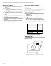
Choosing a location…
When choosing locations for equipment, duct connections,
and fresh air intake, be sure to consult local code
requirements.
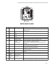
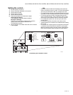
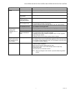
16 REMOTE Remote switch (two
terminals)
24 Vac powered contacts allow a remote switch closure to call for
ventilation.
17 AUX Auxiliary (two terminals) 24 Vac dry contacts allow W8150 to control an auxiliary device, such as
exhaust fan or HRV/ERV, with a call for ventilation.
18 DAMPER Damper (two terminals) 24 Vac powered contacts control fresh air damper.
19 XFMR C 24 Vac ventilation control
common
Supplies power to W8150 and damper from transformer provided.
20 XFMR R 24 Vac ventilation control
power
Supplies power to W8150 and damper from transformer provided.
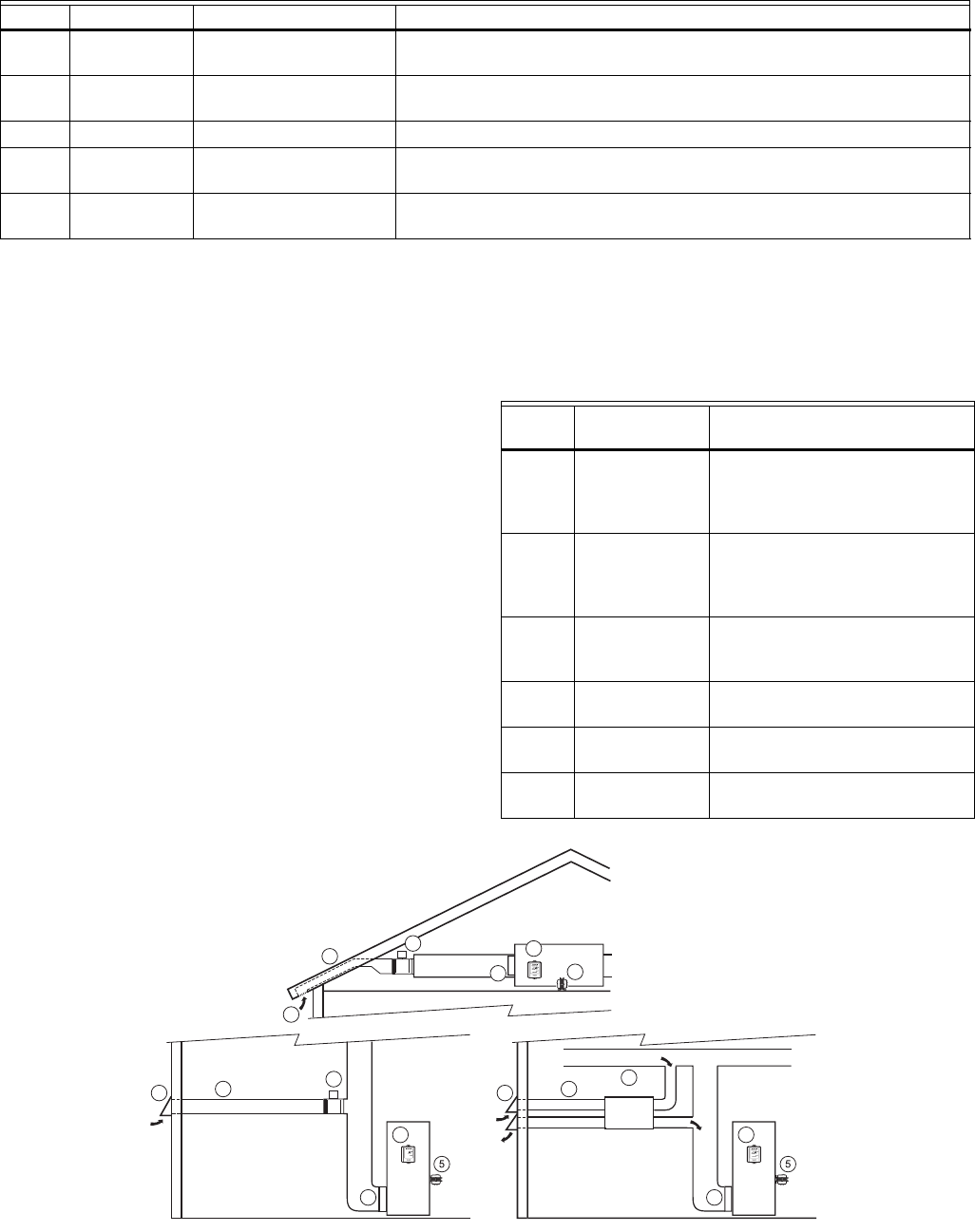
No. Name Description Function
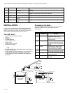
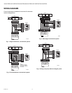
Device
Number Component Location
1 Fresh air intake Install away from known sources
of pollutants such as auto
exhaust, dryer vent exhaust or
chimney smoke.
2 Fresh air duct Install between weather hood and
upstream of equipment filter and
downstream of any duct-mounted
sensor.
3 Damper Install damper in fresh air duct,
where convenient. Optionally,
install heat recovery ventilator.
4 Control Locate the control for convenient
access and for easy wire routing.
5 Transformer Locate where convenient for line
voltage connection.
6 Filter Locate filter downstream of fresh
air intake.
M19993
1
2
1
3
TYPICAL ATTIC
INSTALLATION
TYPICAL BASEMENT
INSTALLATION
TYPICAL HRV/ERV
INSTALLATION
3
2
HRV/ERV
6
6
6
4
4
5
1
3
2
V
e
n
t
il
at
i
o
n
C
o
n
t
r
o
l
V
e
n
t
il
at
i
o
n
C
o
n
t
r
o
l
A
uto
Continuous
(Remote Only)
4