


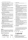

8
Instruction on mounting and use
Consult the designs in the front pages referenced in the text
by alphabet letters.
Closely follow the instructions set out in this manual. All
responsibility, for any eventual inconveniences, damages or
fires caused by not complying with the instructions in this
manual, is declined.
Use
The hood is designed to be used either for exhausting or filter
version.
Ducting version
The hood is equipped with a top air outlet B for discharge of
fumes to the outside (exhaust pipe and pipe fixing clamps not
provided).
Filter version
Should it not be possible to discharge cooking fumes and
vapour to the outside, the hood can be used in the filter
version, fitting an activated carbon filter and the deflector F
on the support (bracket) G, fumes and vapours are recycled
through the top grille H by means of an exhaust pipe
connected to the top air outlet B and the connection ring
mounted on the deflector F (exhaust pipe and pipe fixing
clamps not provided).
To switch from “Vented” to “Ventless” operation, contact your
retailer or the manufacturer for the relevant assembly kit.
The models with no suction motor only operate in ducting
mode, and must be connected to an external suction device
(not supplied).
Installation
The minimum distance between the supporting surface for the
cooking vessels on the hob and the lowest part of the range
hood must be not less than 60cm from electric cookers and
65cm from gas or mixed cookers.
If the instructions for installation for the gas hob specify a
greater distance, this must be adhered to.
Electrical connection
The electrical tension must correspond to the tension noted on
the label placed inside the cooker hood. Connect the electrical
plug, where provided, to the an easily accessible outlet in
conformity with local standards in force. Where an electrical
plug is not provided (for direct connection to electrical
network) or is not easily accessible, place a standards
approved bipolar switch that provide full disconnection under
overvoltage category III conditions, in accordance with the
wiring rules.
Attention: substituting the supply cable must be carried out
by the authorised technical assistance service.
Mounting
Expansion wall plugs are provided to secure the hood to most
types of walls/ceilings. However, a qualified technician must
verify suitability of the materials in accordance with the type of
wall/ceiling. The wall/ceiling must be strong enough to take
the weight of the hood. Do not tile, grout or silicone this
appliance to the wall. Surface mounting only.
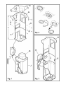
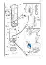
For transportation reasons the upper flue and the lattice girder
are temporarily fixed together with two screws A (fig. 5).
These must be removed and conserved.
Attention! This product envisages a series of installation
operations involving special electric cable connections.
Always check during installation that the passage of these
cables avoids any possible damage to them:
1. Before attaching the hood to the ceiling you need to
decide whether to use the hood in the filtering or suction
version.
The following operations need to be carried out if you
choose the filtering version:
Mount one of the supplied connection rings on deflector F
(Fig. 6) (in any case, the one without non-return fumes
valve, when this is supplied) with two screws.
Note: Mount the connection ring so that the circular hole
is central with respect to the deflector.
Mount deflector F on the upper brackets of the lattice
girder with 4 screws.
2. Remove the 2 C screws (Fig. 1) that temporarily fix the
two parts of the lattice girder together.
Adjust the extension of lattice girder “L”, according to the
following formula:
L = h - (d+44cm)
Where:
L= lattice girder extension,
h = distance between the ceiling and the support
surfaces of the cooking device containers.
d= distance between the lower park of the hood and the
support surfaces of the cooking device containers.
Attention! RESPECT THE MINIMUM DISTANCES
INDICATED IN THIS INSTRUCTIONS BOOKLET.
Fix the lattice girder with the 8 D screws (Fig. 1).
3. Place supplied template E (Fig. 1) onto the ceiling and
make the holes indicated and also prepare the area for
electrical connection.
The side with the arrow on the template corresponds to
the front part of the hood (commands side).
For the suction version only: make the outlet for the
discharge tube and install a tube of sufficient length to
reach the connection ring on the hood motor, when this is
installed.
Insert 4 dowels.
4. Mount the lattice girder onto the ceiling and fix with 4
screws and washers I (Fig. 1).
Attention! The lattice girder has a side: the front is the
part without the hooking fold (see also Fig. 1).
5. Mount the B connection ring (Fig. 1), with the non-return
fumes valve (when supplied) onto the motor housing with
two screws.
Note: Mount the connection ring so that the circular hole