


9
is central with respect to the motor housing.
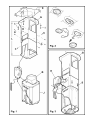
6. Filtering version only: install a section of a tube, long
enough to reach the connection ring on the motor
housing (Fig.1), onto the F deflector.
7. Mount motor housing J (Fig. 1) to the lattice girder with 4
large S screws (Fig. 3) so that the side with the electronic
and connection boxes are on the front part.
8. Connect the discharge tube.
9. Fix bracket K (Fig. 3-Fig. 4-Fig. 4.1), which supports the
electronic box and the connection box, to the motor
housing with 2 screws.
10. Insert the M commands box into apposite N sealing rail
(Fig. 4.2 – Fig. 4.3).
Note! The drawing shows a type of commands box. This
can be equipped with a number of different keys and leds
depending on the model possessed.
11. Connect to the domestic electric power.
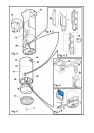
12. Mount upper flue O onto the lattice girder with the 2 A
screws (Fig. 5).
Note: the upper flue is reversible. It is possible to install it
with air exit slit H (Fig. 5) upward (filtering version) or
downward (suction version) so as to be hidden when the
lower flue is mounted (in this case, however, the total
extension of the flues will be reduced).
Attention! Insert the flue carefully so as to avoid
damaging the electric cables and the commands box.
13. Mount lower flue P and fix it to the lower part of the motor
housing with two screws Q (Fig. 5)
Note: Do not tighten completely!
Attention! Insert the flue carefully so as not to avoid
damaging the electric cables and the commands box.
14. Mount spacer ring S (Fig. 5) or the mantel, when
envisaged.
15. Tighten screws Q (Fig. 5) with decision.
16. Remove the carbon filter holding frame and tighten
internal screw R (Fig. 4.3) that adjusts the position of the
commands box so that the keys extrude from the flue.
Block the position tightening the lock nut on the screw.
17. Remove central screw T (Fig. 5), placed between the
bulbs, temporarily and fix filter holder mask U (Fig. 5)
with it.
Operation
Use the high suction speed in cases of concentrated kitchen
vapours. It is recommended that the cooker hood suction is
switched on for 5 minutes prior to cooking and to leave in
operation during cooking and for another 15 minutes
approximately after terminating cooking.
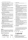
Functioning - 5-key electronic model
123OOI
FC
1234 567 8 9
1. Motor OFF button
2. ON button and motor speed selection button 1 - 2 - 3 - 1 -
2 - . . . .
3. Speed 1 LED
4. Speed 2 LED and metal grease filter saturation LED (in
this latter case, the LED will flash - See instructions on
grease filter cleaning).
Once the grease filters have been cleaned, press button
1 for about 3 seconds until you hear the acoustic signal
(beep): the LED 4 will now stop flashing.
5. Speed 3 LED and active carbon filter saturation LED (in
this latter case, the LED will flash - See instructions on
active carbon filter replacement).
Once you have replaced the charcoal filter, press button
1 for about 3 seconds until you hear the acoustic signal
(beep). LED 5 will now stop flashing.
Warning!
The active carbon filter saturation LED is not activated.
In order to activate the active carbon filter saturation
indicator, press buttons 2 and 7 simultaneously for 3
seconds. Initially, only LED 4 will flash, then after the 3
seconds have passed, LED 5 will also start flashing,
indicating that the active carbon filter saturation control
system is active.
To switch off the system, re-press the same two buttons:
after 3 seconds LED 5 will stop flashing and the device
will be switched off.
6. Intensive speed LED
7. Intensive speed ON switch
This speed should be used when the concentration of
cooking fumes or odours is particularly strong (for
example when frying, cooking fish etc.).
The fast speed will run for about 5 minutes and then
return to the speed previously set automatically (1, 2 or
3), or switch off if no speed was selected.
To turn off the fast speed, before the end of the 5
minutes, press button 1 or button 2.
8. OFF lamp button
9. ON lamp button
If the hood fails to operate correctly, briefly disconnect it
from the mains power supply for almost 5 sec. by pulling
out the plug. Then plug it in again and try once more
before contacting the Technical Assistance Service.
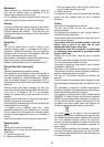
Model with button panel
DCBAE
A. on/off light switch
B. on/off aspiration switch and minimum power selection
B+C. medium power selection aspiration switch
B+D. maximum power selection aspiration switch
E. operating gauge (foreseen in the model with round buttons)