


32
Defrost Termination: Has DTh warmed to 59°F (15°C)? If not yet conrmed, conrm
DThstatus.See"IV.C.ThermistorCheck."IfDThisgoodbutdefrosttermination
temperature is not reached, conrm DH amp draw and continuity. If DTh is good and
defrost termination temperature is reached, DH de-energizes and 3 delay timers start.
3-minute Comp delay timer terminates: Have Comp and ConFM energized after DH
is de-energized for 3 minutes? If not, check for 115VAC between CM C1 and CM N5.
If 115VAC is not present, CM is defective and must be replaced. If 115VAC is present
between CM C1 and CM N5, check for 115VAC on CR coil (terminals 5 and 6). If
115VAC is not present between CR5 and CR 6, check continuity of HPS. If open, allow
time for HPS to reset. If HPS does not reset, replace HPS and diagnose reason for
HPSactivation.See"IV.A.2.7)c)HPSActivation."If115VACispresentbetweenCR5
and CR 6, and Comp and ConFM are not energized, check for 115VAC between CR
terminal 4 and neutral and CR terminal1 and neutral. If 115VAC is present between
CR terminal 4 and neutral and not CR terminal 1 and neutral, CR is defective and must
be replaced. If CR is good and Comp or ConFM are not energized, check for 115VAC
at Comp terminals, Comp overload (internal on 1-section, external on 2-section), start
components, and Comp and ConFM motor winding continuity.
8-minute EvapFM delay timer terminates (3-minutes on manually initiated defrost):
Have EvapFM energized 5 minutes after Comp and ConFM energized? If not, conrm
that the door(s) are closed and DS contacts are closed. Check EvapFM blades for
binding. Next, checkfor 115VAC at DSR terminals 7 and 8. If 115VAC is not present,
check DS continuity. If 115VAC is present, check DSR coil continuity and contact
continuity between terminals 6 and 4. If coil or contacts are open, DSR is bad and must
be replaced. Next, check for 115VAC between CM F6 and CM N5. If 115VAC is not
present, check between CM L3 and CM N5. If 115VAC is present between CM L3 and
CM N5 and not between CM F6 and CM N5, CM is defective and must be replaced. If
115VAC is present between CM F6 and CM N5, check EvapFM continuity.
13-minute temperature display delay timer terminates: Conrm cabinet temperature
appears on DM 5 minutes after EvapFM energizes.
If components fail to start after delay timer terminates, CM is defective and must be
replaced.
10) MH and PH Diagnosis: Check that MH and PH energize. Check for 115VAC at MH
and PH. If 115VAC is not present, check power supply and continuity of power switch.
If 115VAC is present, check amp draw of MH or PH. If an amp reading is not present,
check the continuity of MH or PH.
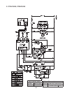
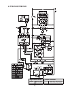
Legend: CM–control module; Comp–compressor; ConFM–condenser fan motor;
CR–compressor relay; CTh–cabinet thermistor; DH–defrost heater;
DM–display module; DSR–door switch relay; DTh–defrost thermistor;
EvapFM–evaporator fan motors; HPS–high-pressure switch; MH–mullion
heater; PH–perimeter heater; TXV–thermostatic expansion valve