


14
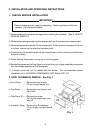
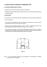
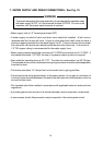
7. WATER SUPPLY AND DRAIN CONNECTIONS - See Fig. 10
WARNING
To prevent damage to the pump assembly, do not operate the icemaker when
the water supply is OFF, or if the pressure is below 10 PSIG. Do not run the
icemaker until the proper water pressure is reached.
• Water supply inlet is 1/2" female pipe thread (FPT).
• A water supply line shut-off valve and drain valve should be installed. A ball valve is
recommended for the shut-off valve. A type of valve other than a ball valve can have a
maximum opening smaller than the water supply line ID. This can cause a too low water
flow rate which can lead to poor defrost performance and/or freeze up. A minimum of
1/2" OD copper tubing is recommended for the water supply lines.
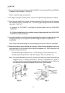
• Water supply pressure should be a minimum of 10 PSIG and a maximum of 113 PSIG. If
the pressure exceeds 113 PSIG, the use of a pressure reducing valve is required.
• Drain outlet for icemaker dump is 3/4" FPT. The drain for condensation is a 3/8" ID pipe.
The icemaker drain and the condenser drain piping connections must be made separately
from the bin drain.
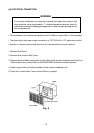
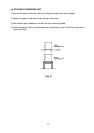
• The drains must have 1/4" fall per foot on horizontal runs to get a good flow.
• The drains should not be piped directly to the sewer system. An air gap of a minimum of
2 vertical inches should be between the end of the drain pipe from the icemaker or the ice
bin and the floor drain.
• This icemaker should be installed in accordance with applicable national, state and local
regulations.
• A plumbing permit and services of a licensed plumber may be required in some areas.
• In some areas, a back flow preventer may be required in the cooling water circuit.