


22
4. Control Board Check Procedure
Before replacing a control board that does not show a visible defect and that you suspect
is bad, always conduct the following check procedure. This procedure will help you verify
your diagnosis.
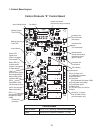
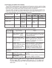
1) Check the dip switch settings to assure that #3, 4, 7, 8, 9, & 10 are in the factory default
position. On units with a slide-type output test switch, the output test switch (S3) should
be OFF. Switches 1, 2, 5, & 6 are cleaning adjustments and the settings are flexible.
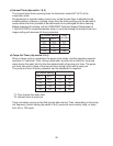
2) Turn the control switch to ICE and check for proper control voltage. If the red LED is ON,
the control voltage is good. If the red LED is OFF, check the control transformer circuit.
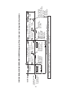
3) Check the 115 volt input at the 10-pin connector. Check the brown wire at pin #10 to a
white neutral wire for 115 volts. (Always choose a white neutral wire to establish a good
neutral connection when checking voltages.) A jumper also feeds 115 volts into pin #7.
If no voltage is present, check the 115 volt supply circuit.
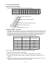
4) The output test switch provides a relay sequence test. On units with a slide-type output
test switch, move the control switch to the OFF position, move the output test switch to
the ON position, then move the control switch to the ICE position. On units with a push-
type output test switch, make sure the control switch is in the ICE position, then press
the output test switch. The correct lighting sequence should be none, 2, 3, 4, 1, and 4,
normal sequence every 5 seconds. Components (e.g., the compressor) will cycle during
the test. Note that the order of the relays from the outer edge of the board is 1, 4, 3, 2.
Note: If the LEDs light in a different sequence or the 5–second interval does not occur,
the control board is bad and should be replaced.
5) After checking the sequence, place the output test switch back in the OFF position
on units with a slide-type switch. The output test switch must remain in the OFF
position during normal operation. On units with a push-type output test switch, the unit
automatically resumes normal operation after the test. The unit begins normal operation
with the 1 minute fill cycle.
5. Control Board Replacement
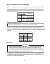
The application switch located between relay X3 & X4 must be set to match the original
board application. Place this switch in the ALP position if there is no white wire supplied
to the K1 connector. If there is a white wire, place the switch in the C position. If this
switch is placed in the wrong position either the compressor contactor will remain
energized with the control switch OFF or the unit will not start.
The dip switches should be adjusted to the factory default settings as outlined in this
manual. Dip switch #8 must remain in the OFF position.