


28
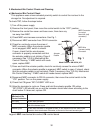
f) Refrigerant Pressures, HM, and TXV Diagnosis: If evaporator is still not cooling,
check refrigerant pressures. See "VIII.B. Performance Data."
Next, check HM operation. If refrigeration pressures are above HM setpoint and
HMis bypassing, replace HM. Check TXV for proper operation. Remove TXV bulb
and hold it in your hand, refrigerant low-side pressure should rise, place TXV bulb in
ice water, refrigerant low-side pressure should drop. A 10 to 15 pound pressure swing
between warm and cold conditions indicate a good TXV. If a 10 to 15 pound swing is
not present, replace TXV.
g) WRV Diagnosis: WRV is factory set and generally no adjustment is required.
IfWRV fails to open in freeze, check for proper refrigerant pressures. See "VIII.B.
Performance Data." If refrigerant pressures are correct and WRV does not open,
adjust or replace as needed. See "IV.C. Water Regulating Valve Adjustment
(water-cooled models)."
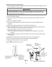
h) Freeze Termination Diagnosis: After 5 min. in freeze, disconnect CB K5 FS
connector. 15 sec. later appliance should switch out of the freeze cycle (15 second
delay after FS opens before terminating the freeze cycle). If appliance remains in
freeze longer than 15 sec. after FS removed, replace CB. If appliance switches with
FS removed but would previously not switch out of freeze with FS connected (long
freeze - 3 beep alarm), see "II.E. Float Switch Check and Cleaning."
Note: Normal freeze cycle will last 20 to 40 min. depending on model and conditions.
Cycle times and pressures should follow performance data provided in this
manual. See "VIII.B. Performance Data."
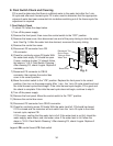
i) Short Freeze Cycle Diagnosis: Conrm water tank lls and overows during 1 min.
ll and harvest cycles. If not, check water supply lters, shut-off valve, WV screen.
Ifwater tank empties before 5 min. timer terminates and freeze cycle is short, check
that CV is not leaking by (water owing down the potable drain). If CV is leaking by,
remove and clean CV, replace rubber seat and spring if necessary. If water tank is
full, see "II.E. Float Switch Check and Cleaning." for erratic operating FS.
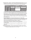
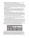
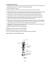
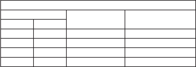
7) Pump-Out Cycle – LEDs 1, 3, and 2 are on (10/20 second pump-out). Timing of the
rst pump-out is determined by S4 dip switch 5& 6. See the table below.
"G" Control Board Settings
S4 Dip Switch Setting
Pump-Out
Frequency
"G" Control Board
No. 5 No. 6
OFF OFF Every cycle After 2nd freeze cycle
ON OFF Every 2 cycles After 3rd freeze cycle
OFF ON Every 5 cycles After 6th freeze cycle
ON ON Every 10 cycles After 11th freeze cycle
Comp and FMR continue, HGV energizes. If S4dip switch 3 & 4 are set to 3 off
and 4 on, LED 4 turns on and WV and X11 relay energize, energizing X10relay.
NOTICE!S4dip switch 3 & 4 must not be set to 3 off and 4 on. Otherwise, PM
will rotate in freeze cycle direction instead of pump-out direction. FM and LLV
de-energize. PM stops for 2 sec., then reverses for 10/20 sec. depending on pump-out
timer (S4dip switch 3 & 4) setting. When the pump-out timer terminates, pump-out