54
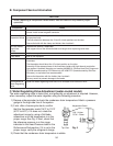
B. Component Service Information
NOTICE
When replacing a component listed below, see the notes to help ensure proper
operation.
Component Notes
Compressor 1 phase: Install a new start capacitor, run capacitor, and start relay.
3 phase: Install a new magnetic contactor.
Thermostatic
Expansion Valves
• Attach the thermostatic expansion valve bulb to the suction line in the same location as
the previous bulb.
• The bulb should be between the 10 and 2 o'clock positions on the tube.
• Secure the bulb with the clamp and holder, then insulate it.
Hot Gas Valves
Liquid Line
Valves
• Replace the strainer if applicable.
• Use copper tube of the same diameter and length when replacing valve lines.
Fan Motors Install a new capacitor.
Pump Motor Install a new capacitor.
Thermistor • Attach the new thermistor to the suction line in the same location as the previous
thermistor.
• The thermistor should be at the 12 o'clock position on the tube.
• Smoothly ll the recessed area of the thermistor holder with high thermal conductive
type sealant. Hoshizaki America part number 4A0683-01 (Silicone Heat Sink Compound
10-8108 manufactured by GC Electronics), KE-4560 RTV (manufactured by ShinEtsu
Silicones), or equivalent are recommended.
• Secure the thermistor with the holder, then insulate it.
• Be very careful to prevent damage to the leads.
KM-650MWH-M
Water Regulating
Valve
Tighten the water regulating valve are nut to a torque of 39.8 ft-lb/53.9N·m.
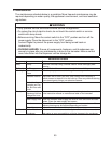
C. Water Regulating Valve Adjustment (water-cooled model)
The water regulating valve is factory set, and generally no adjustment is required. However,
when necessary, adjust the water regulator using the following procedure.
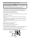
1) Prepare a thermometer to check the condenser drain temperature. Attach a pressure
gauge to the high-side line of the system.
2) 5 min. after a freeze cycle starts, conrm
that the thermometer reads 104°F to 115°F
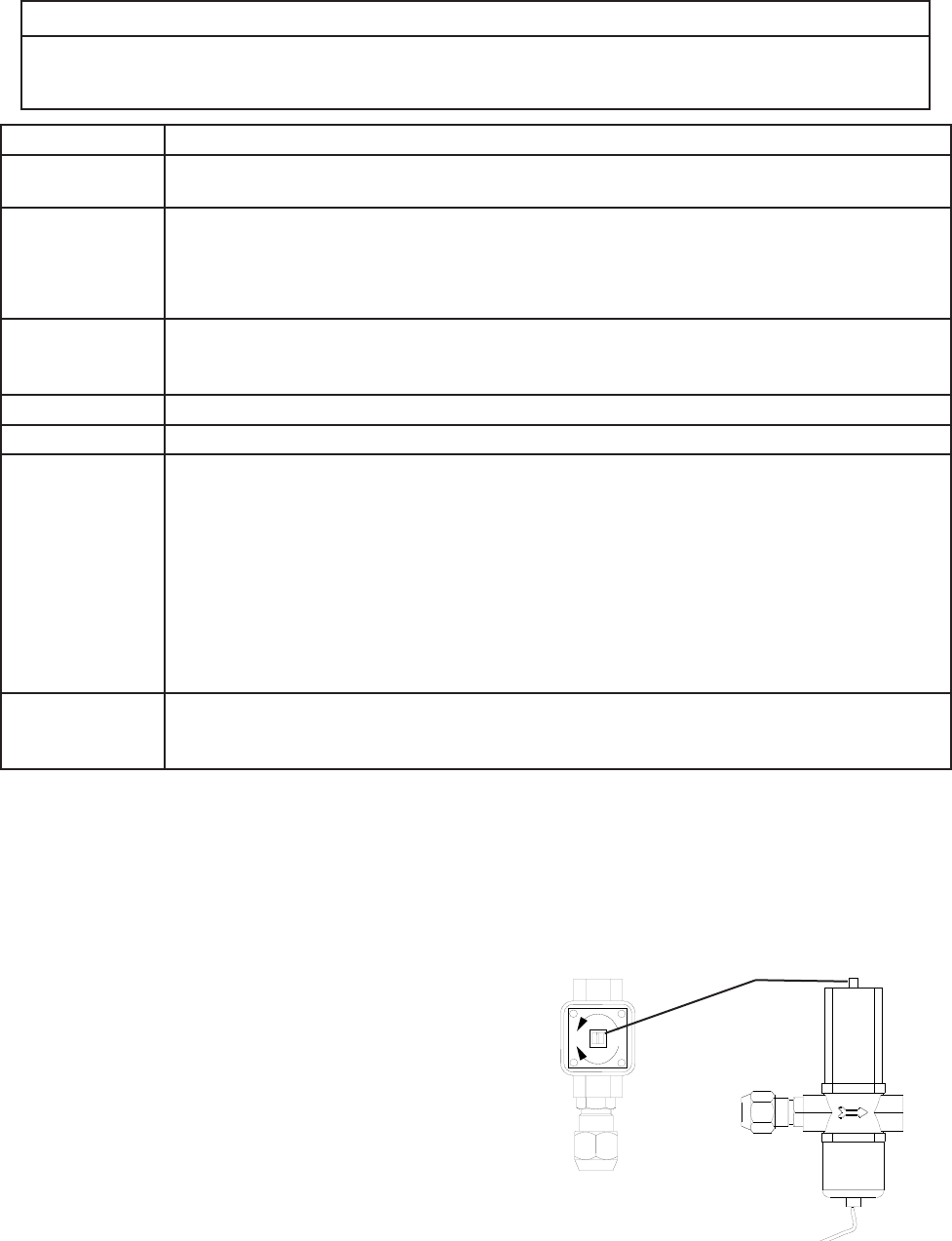
(40°C to 46°C). If it does not, rotate the
adjustment screw by using a at blade
screwdriver until the temperature is in the
proper range. See Fig. 5. Next, check that
the reference pressure is in the range
indicated in the Head Pressure table in the
Performance Data section. If it is not in the
proper range, verify the refrigerant charge.
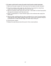
3) Check that the condenser drain temperature is stable.
Fig. 5
Adjustment Screw
CW – Higher
CCW – Lower
Top View


