


7
GB
PLEASE PHONE US TO REGISTER YOUR APPLIANCE AND ACTIVATE YOUR PARTS GUARANTEE ON 08448 24 24 24
Installation
STABILITY CHAIN
A hole in the gas inlet valve bracket can be used to
engage a stability chain.
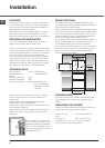
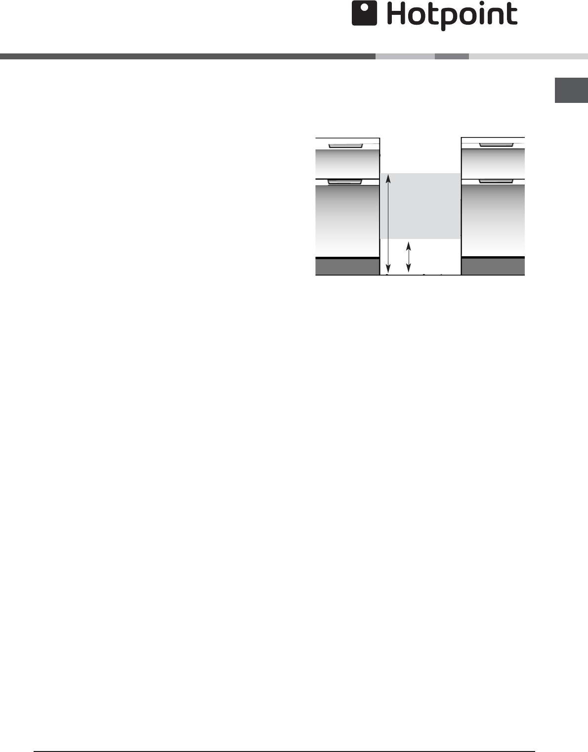
CONNECTING TO GAS SUPPLY
300
670
Connection to the cooker should be made with an
approved appliance flexible connection to BS 669. A
length of 0.9 to 1.25m is recommended. The length of
hose chosen should be such that when the cooker is in
situ, the hose does not touch the floor.
Those cookers converted to use on LPG should be
connected with a hose suitable for LPG and capable of
withstanding a pressure of 50 mbar.
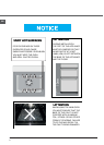
An adaptor backplate should be fitted within the
shaded area shown, to allow the cooker to be pushed
fully to the wall and to ensure that the flexible hose is
only likely to come into contact with areas at the rear
of the cooker that do not exceed a temperature rise of
70°C.
LEVELLING
Four skid feet are fitted which can be adjusted up or
down to level the cooker.
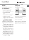
CONVERSION FOR USE ON BUTANE
(G30) OR PROPANE (G31)
Each burner requires the injector to be replaced and
bypass screws adjusted or replaced as follows:
1. Remove the loose hotplate burner parts.
2. Using a 7mm socket, replace the hotplate injectors
as appropriate (see table on previous page).
3. Re-position the loose burner parts.
4. Remove the enamelled baffle at the front of the grill
(2 screws).
5. Remove the screw on the right hand side of the
burner and gently slide the burner off the injector.
6. Using a 7mm socket, replace the grill injector as
appropriate (see table on previous page).
7. Re-assemble the burner and baffle.
8. Inside the top oven, remove the central screw se-
curing the burner retainer. Slide the retainer to the
right slightly and lift away.
9. Lift the burner assembly and place on the floor of
the oven to the right of the burner opening.
10. Using a 7mm socket, replace the oven injector as
appropriate (see table on previous page).
11. Re-assemble the oven burner and retainer.
12. Replace the main oven injector following the same
procedure as for the top oven.
13. Carefully pull off the control knobs and timer but-
tons.
14. Remove the 2 screws securing the underside of
the control panel. Slide the control panel to the left
slightly to remove.
15. Remove the 6 screws securing the timer mounting
panel. Without completely removing it, manoeuvre
the timer mounting panel to gain access to the
thermostat bypass screws.
16. Using a narrow flat bladed screwdriver rotate the
bypass screws fully clockwise. The main oven
thermostat bypass screw is located on the body
of the thermostat below the spindle, the top oven
thermostat bypass screw is located on the body of
the thermostat to the right of the spindle and the
hotplate tap bypass screws are located down the
centre of the spindle.
17. Re-assemble the control panel parts ensuring that
when the connections are made to the ignition
switch, the wires are above the switch rather than
below.
18. Secure the self-adhesive LPG conversion label over
the gas details on the data badge.