


13
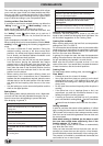
The following instructions are provided for qualified installers
so that they may carry out installation, adjustment and
technical maintenance operations correctly and in
compliance with the applicable norms in force.
Important: Disconnect the appliance from the electrical
and gas supply before performing any maintenance or
repair.
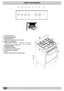
The cooker has the following technical specifications:
- Cat. II2H3+
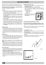
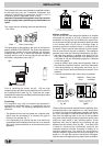
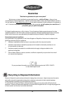
The dimensions of the appliance are given in the figure on
page 5, 'KNOW YOUR COOKER'. For trouble-free operation
of appliances installed in furniture cabinets, the minimum
distances shown in fig. 5 should be observed. Adjacent
surfaces and the wall at the rear should also be able to
withstand a temperature rise of 65 °C.
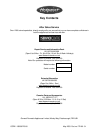
Prior to installing the cooker, the 95 - 155 mm high
supporting feet (provided) should be fitted into the holes to
be underneath the cooker (fig. 6). These feet are screw-
adjustable and whenever necessary should be used to make
sure the cooker is level.
Positioning
This appliance may only be installed and operated in
permanently ventilated rooms in compliance with the
regulation s in force. The following requirements must be
observed:
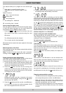
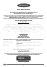
• The appliance must vent flue gases into a special hood,
which must be connected to a chimney, flue pipe or
directly to the outside (fig. 7).
• If it is impossible to fit a hood, the use of an electric fan
is permitted, either installed on a window or on an external
wall, which must be switched on at the same time as the
appliance.
INSTALLATION
fig.6
Kitchen ventilation
The air flow into the room where the appliance is installed
must equal the quantity of air that is required for regular
combustion of the gas and for ventilating the same room.
Air must enter naturally through permanent apertures made
in the outside walls of the room or through single or
branching collective ventilation ducts in compliance with
the norms. The air must be taken directly from the outside,
from an area far from sources of pollution. The ventilation
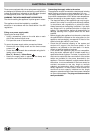
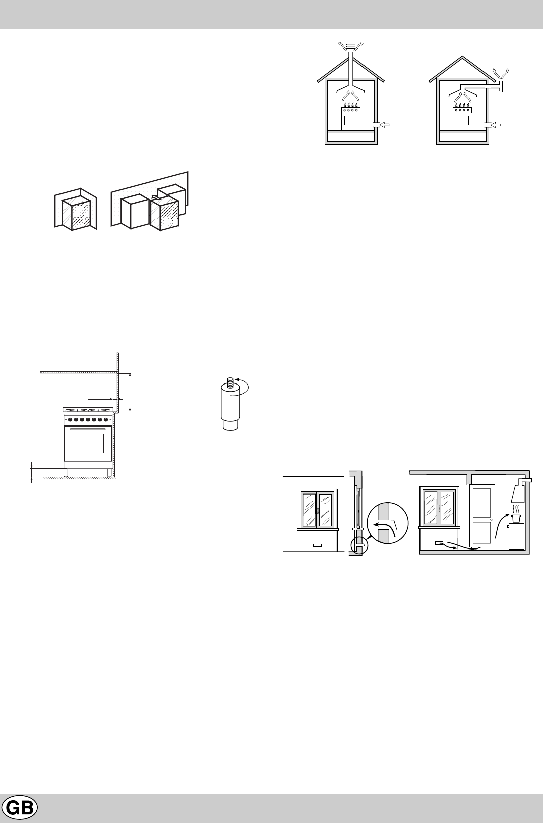
aperture must have the following characteristics (fig. 8A):
• total free cross section of passage of at least 6 cm² for
every kW of rated heating capacity of the appliance, with
a minimum of 100 cm² (the heating capacity is indicated
on the rating plate);
• it must be made in such a way that the aperture, both on
the inside and outside of the wall, cannot be obstructed;
• it must be protected, e.g. with grates, wire mesh, etc. in
such a way that the above-mentioned free section is not
reduced;
• it must be situated as near to floor level as possible.
Detail A Adjacent Room to be
room ventilated
Examples of ventilation Enlarging the ventilation slot
holes for comburant air between window and floor
fig. 8A fig.8B
The air inflow may also be obtained from an adjoining room,
provided the latter is not a bedroom or a room where there
is a risk of fire, such as warehouses, garages, fuel stores,
etc. and is ventilated in compliance with the norms. The air
flow from the adjoining room to the one to be ventilated
may pass freely through permanent apertures with a cross
section at least equal to that indicated above. These
apertures may also be obtained by increasing the gap
between the door and the floor (fig. 8B). If an electric fan
is used for extracting the combustion products, the
ventilation aperture must be increased in relation to its
maximum performance. The electric fan should have a
sufficient capacity to guarantee an hourly exchange of air
equal to 3 ÷ 5 times the volume of the kitchen. Prolonged,
intensive use of the appliance may require extra ventilation,
fig.7
fig.5
95÷155mm
min. 100mm
min. 700mm
A
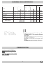
Class 1 Class 2 sub-class 1
In a chimney stack or branched flue Directly to the outside
(reserved for cooking appliances