


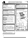
INSTALLATION INSTRUCTIONS
(continued)
❑
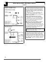
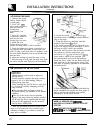
LEVELING THE RANGE
1.
Remove the storage
drawer, broiler drawer
or kick panel.
2. Use a 3/16”
open-
end or socket wrench to
back out both rear
leveling legs
approximately two
turns.
3. Use a l%” open-end
or adjustable wrench to
back out the front
leveling legs two turns.
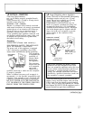
4. Install the oven
shelves in the oven and
position the range where it will be installed.
5. Check for levelness by placing a spirit level or a
cup, partially filled with water, on one of the oven
racks. If using a spirit level, take two readings—with
the level placed diagonally first in one direction and
then the other.
6. Adjust the leveling legs until the range is level.
7. After the range is level, slide the range away from
the wall so that the Anti-Tip device can be installed.
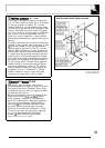
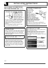
❑
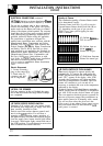
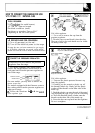
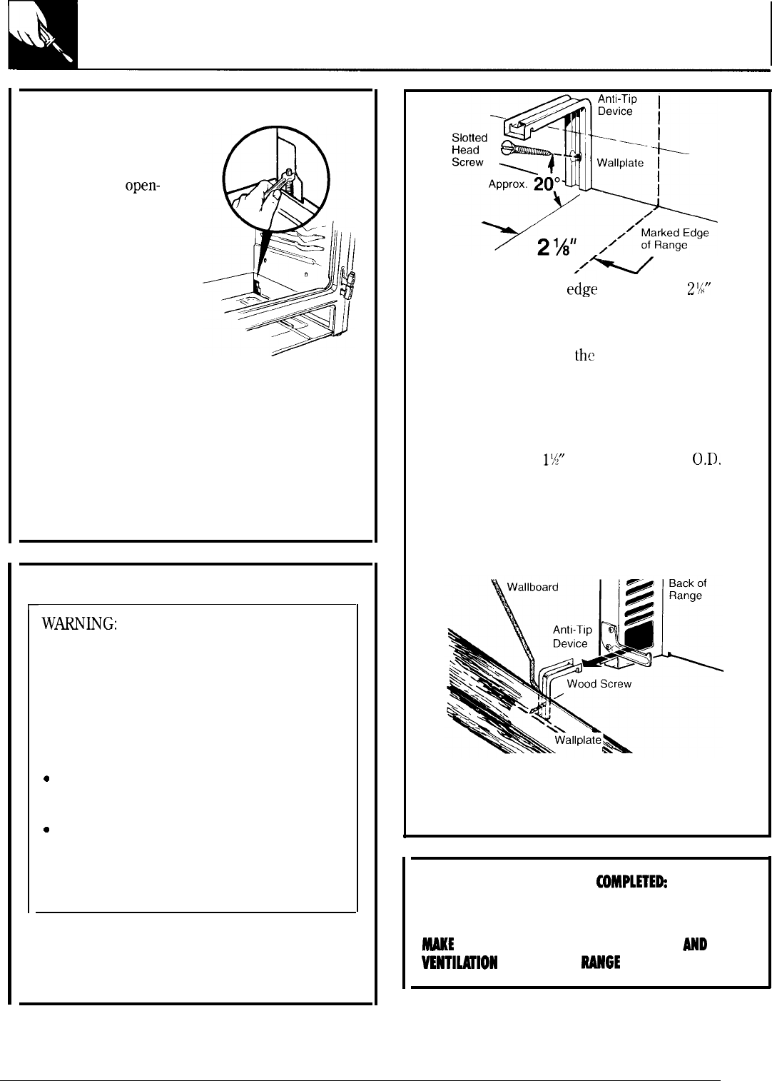
INSTALLING THE ANTI-TIP DEVICE
r
1.
Mark the wall where the RIGHT EDGE of the
range is to be located. Be sure to allow for the
countertop overhang if you intend to install the
range next to cabinets.
W~ING:
●
Range must be secured with an approved
Anti-Tip device.
●
Unless properly installed, the range could be
tipped by you or a child standing, sitting or
leaning on an open door.
●
After installing the Anti-Tip device, verify that
it is in place by carefully attempting to tilt the
range forward.
c
This range has been designed to meet all
recognized industry tip standards for all normal
conditions.
c
The use of this device does not preclude
tipping of the range when not properly installed.
●
If the Anti-Tip device supplied with the range
does not fit this application, use the universal
Anti-Tip device WB02X7909.
“v
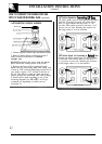
2.
Locate the outside
e~ge
of the device
2%”
toward the center of the range from the marked
edge of the range.
3. Using the device as a template, mark the
position of the hole for
the
screw.
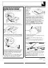
4. For wood construction, drill a pilot hole at an
angle of 20 degrees from the horizontal. A nail or
awl may be used if a drill is not available.
Mount the Anti-Tip device with the screw provided.
For cement or concrete construction, you
will need a 1/4” x
1X”
lag bolt and a 1/2”
0.D.
sleeve anchor, which are not provided. Drill
the recommended size hole for the hardware.
Install the sleeve anchor into the drilled hole and
then install the lag bolt through the device. The
bolts must be properly tightened as recommended
for the hardware.
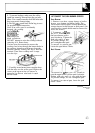
5. Slide the range against the wall, and check for
proper installation by grasping the front edges of
the rear surface unit openings and carefully
attempting to tilt the range forward.
WHEN ALL HOOKUPS ARE
COMPLETEh
MAKE SURE ALL CONTROLS ARE LEFT IN THE OFF
POSITION.
MhKE
SURE THE FLOW OF COMBUSTION
AHD
VENTl~lON
AIR TO THE
RAHGE
IS UNOBSTRUCTED.
40