


6
Hunter Fan Company 42400-01 • 09/26/05
7
42400-01 • 09/26/05 Hunter Fan Company
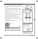
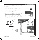
4 • Wiring the Fan
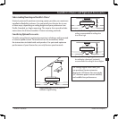
Wire Nut
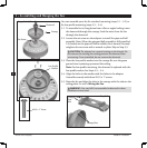
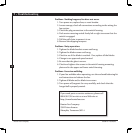
Step 4-3
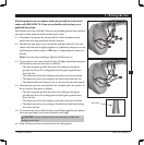
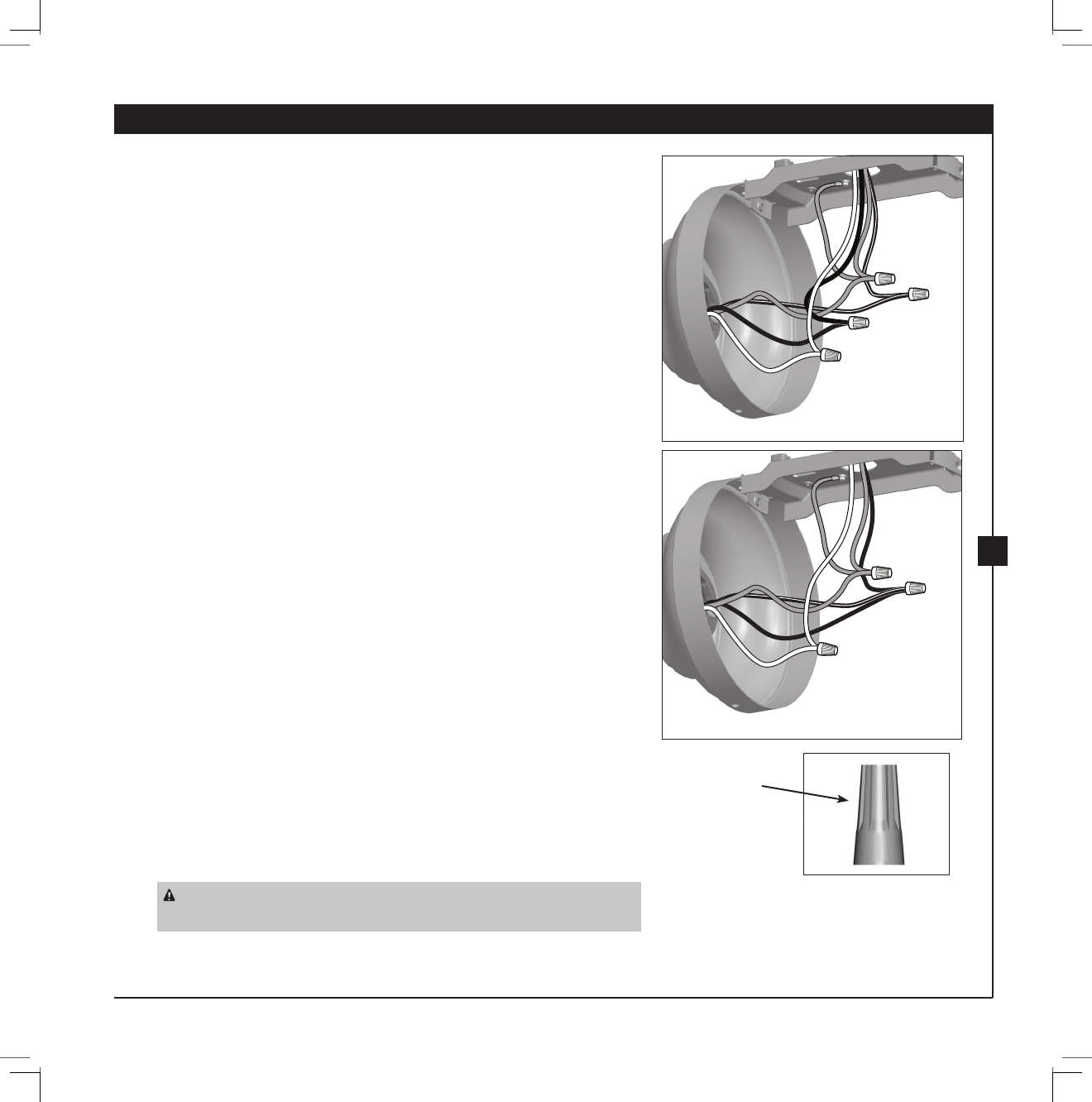
Step 4-4
All wiring must be in accordance with national and local electrical
codes and ANSI/NFPA 70. If you are unfamiliar with wiring, use a
qualied electrician.
Wall switches are not included. Select an acceptable general-use switch in
accordance with national and local electrical codes.
4-1. Disconnect the power by turning o the circuit breakers to the
outlet box and associated wall switch location.
4-2. Decide how you want to set up the fan and light controls. You can
control the fan and/or lights together or separately using one or two
wall switches. Follow Step 4-3 OR Step 4-4, depending on what you
decide.
Note: If you are not installing a light kit, follow step 4-4.
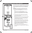
4-3. If you want to, you can control the fan and light separately using two
wall switches, connect the wires as follows:
• e bare or green ground wire from the ceiling to the green
ground wire from the ceiling plate and the green ground wire
from the fan
• e white wire from the ceiling to the white wire from the fan
• e black wire from the ceiling to the black wire from the fan
• e black/white wire from the fan to the wire for the wall switch
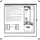
4-4. Alternatively, you can control both fan and light with one switch. To
do so connect the wires as follows:
• e bare or green ground wire from the ceiling to the green
ground wire from the ceiling plate and the green ground wire
from the fan
• e white wire from the ceiling to the white wire from the fan
• e black wire from the ceiling to the black and the black/white
wire from the fan
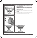
4-5. To connect the wires, hold the bare metal leads together and place a
wire nut over them, then twist clockwise until tight.
CAUTION: Be sure no bare wire or wire strands are visible after
making connections.
4-6. Push all wires and wire nuts back into the ceiling plate.