


Rev.0210
7
REFRIGERANT TYPE
The standard refrigerant will be R-22 unless otherwise
specified on the customer order. Check the serial plate
on the case for information.
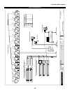
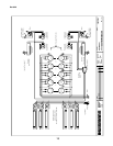
PIPING
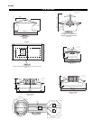
The refrigerant line outlets are located under the case.
Locate first the electrical box, the outlets are then on the
same side of the case but at the opposite end. Insulate
suction lines to prevent condensation drippage.
ACCESS PANELS
All electrical and drain access panels are clearly labeled
on the deck of the produce stand. The access for con-
densing units (in the self contained units) is located on the
side of the stand, at the end. Ends of stand are fitted for
removal, if condensing unit has to be taken out.
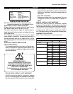
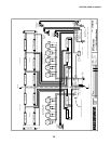
REFRIGERATION LINES
LIQUID SUCTION
3/8" O.D. 5/8" O.D.
NOTE: The standard coil is piped at 5/8" (suction); however,
the store tie-in may vary depending on the number of
coils and the draw the case has. Depending on the case
setup, the connecting point in the store may be
5
/8",
7
/8", or 1
1
/8". Refer to the particular case you are
hooking up.
Refrigerant lines should be sized as shown on the refrig-
eration legend furnished by the store.
Install P-traps (oil traps) at the base of all suction line ver-
tical risers.
Pressure drop can rob the system of capacity. To keep the
pressure drop to a minimum, keep refrigerant line run as
short as possible, using the minimum number of elbows.
Where elbows are required, use long radius elbows only.
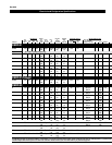
CONTROL SETTINGS
See the “Case Specs” section of this guidebook for the
appropriate settings for your merchandiser. Maintain these
parameters to achieve near constant product tempera-
tures. Product temperature should be measured first thing
in the morning, after having been refrigerated overnight.
For all multiplexing, defrost should be time terminated.
Loadmaster valves are not recommended. Defrost times
should as directed in the Case Specifications section of
this guide. The number of defrosts per day should never
change. The duration of the defrost cycle may be adjusted
to meet conditions present at your location.
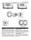
ACCESS TO TX VALVES & DRAIN LINES
MECHANICAL - Remove product from end of case. Remove
product racks. Remove refrigeration and drain access panels
(labeled). TX valve (mechanical only) and drain are located
under each access panel at end of the case.
ELECTRONIC - The Electronic Expansion valve master and
slave cylinder(s) are located within the electrical access
panel(s).
ELECTRONIC EXPANSION VALVE (OPTIONAL)
A wide variety of electronic expansion valves and case
controllers can be utilized. Please refer to EEV and con-
troller manufacturers information sheet. Sensors for elec-
tronic expansion valves will be installed on the coil inlet,
coil outlet, and in the discharge air. (Some supermarkets
require a 4th sensor in the return air). Case controllers
will be located in the electrical raceway or under the case
THERMOSTATIC EXPANSION VALVE LOCATION
This device is located on the same side as the refrigera-
tion stub. A balanced port expansion valve model is fur-
nished as standard equipment, unless otherwise specified
by customer.
EXPANSION VALVE ADJUSTMENT
Expansion valves must be adjusted to fully feed the evapo-
rator. Before attempting any adjustments, make sure the
evaporator is either clear or very lightly covered with frost,
and that the fixture is within 10°F of its expected operat-
ing temperature.
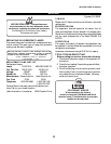
MEASURING THE OPERATING SUPERHEAT
1. Determine the suction pressure with an accurate
pressure gauge at the evaporator outlet.
2. From a refrigerant pressure temperature chart,
determine the saturation temperature at the
observed suction pressure.
3. Measure the temperature of the suction gas at the
thermostatic remote bulb location.
4. Subtract the saturation temperature obtained in step
No. 2 from the temperature measured in step No. 3.
3. The difference is superheat.
5. Set the superheat for 5°F - 7°F.
T-STAT LOCATION
T- Stats are located under access panels on the end of the
case.
Refrigeration