


11 166240009
ELECTRICAL CIRCUIT
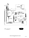
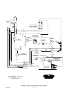
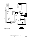
CIRCUIT DESCRIPTION
As the manual on–off–circuit breaker switch is pushed to ”on”, an electrical circuit is completed to the
gearmotor via the circuit breaker gearmotor overload, power relay / contactor, gearmotor delay thermostat and
the bin thermostat. After the previous circuit has been completed the condenser fan motor will start as will the
compressor (via the high pressure control and the compressor starting relay).
COMPONENT DESCRIPTION
BIN THERMOSTAT
This is electrically in ”series” with the ice making system. when the bin is full, the contact opens, terminating
power to the machine.
GEARMOTOR START RELAY
This is a current type relay which means as the gearmotor run winding comes ”on” the line, the current draw
initially is relatively heavy through the relay coil (coil is in series with run winding). It then acts like a normal
relay and the N.O. start contact ”makes”, completing a circuit through the start capacitor to the start winding.
As the gearmotor picks up speed, the amp draw through the relay coil drops off allowing the armature to return
to its normal position (start contact ”opens”). This action removes the start winding from the circuit.
POWER RELAY / CONTACTOR
This relay controls the compressor power only.
GEARMOTOR DELAY THERMOSTAT
This thermostat keeps the gearmotor running until the suction line temperature reaches 45_ after the full bin
switch terminates power to the power relay / contactor.
ON–OFF SWITCH / CIRCUIT BREAKER
This switch interrupts power to the entire unit. The switch has a circuit breaker incorporated into its’ design.
This circuit breaker will trip out in the event the gearmotor draws to high of amps In such an event the power is
interrupted to the unit. To reset the circuit breaker and reestablish power to the unit, push the switch to the ”off”
position and then back to the ”on” position.
FAN CYCLING SWITCH (R404a Units)
The function of this switch is to maintain condensing pressures at a satisfactory level during–low ambient
conditions. The switch breaks the circuit to the condenser fan motor at 205 PSI and makes the circuit at 275
PSI.
HIGH PRESSURE CONTROL
The high pressure cut out is electrically in series with the power relay. As the head pressure rises to 450 PSIG
for R404a charged units and 400 PSIG for R 22 charged units, a preset level, the contact opens thus breaking
the circuit to the compressor via the power relay contactor. This control must be reset manually on R404a units.