


2569000264
NOTE: Only qualified Personnel should install this Kit.
1. Disconnect Unit product inlet lines from product tanks, then open dispensing valves to relieve systems
pressures.
2. Disconnect electrical power from the Unit, open hinged top cover, then drain water tank.
CAUTION: Never use an ice pick or other instrument to remove ice from the refrigeration
system evaporator coils. Such practice can result in a punctured refrigeration circuit.
3. Allow ice to melt from the evaporator coils. Hot water may be used to speed up melting. All ice must be
melted from the evaporator coils.
4. Remove screws securing handle on the Unit, then remove handle.
5. Disconnect large black terminals labeled “A”, “B”, and “C” from the ice bank control module.
6. Remove screws securing the ice bank control module to the agitator motor assembly bracket.
7. Remove screw securing ice bank control module ground wire (connected to the large black terminal labeled
“A”) to the agitator motor assembly bracket.
8. Disconnect the large black terminals electrical wires connectors from Unit wiring harness connectors.
9. Disconnect large black terminal labeled “D” from terminal on ice bank control labeled “D”. Retain old ice
bank control which is to be returned to IMI Cornelius INC.
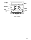
10. Disconnect product source product inlet lines from fittings on top of the agitator motor assembly bracket
(see Figure 3).
11. Remove hex nuts and white plastic washers securing Unit product inlet lines fittings in the agitator motor
assembly bracket.
12. Remove and retain six screws securing the agitator motor assembly bracket to the Unit, then remove agita-
tor motor assembly bracket from the Unit.
13. Disconnect product tubes from backs of the dispensing valves, then lift product coils assembly up out of
the Unit.
14. Remove old ice bank control probe and ice bank control probe holder from the evaporator coil. Retain old
ice bank control probe and probe holder which are to be returned to IMI Cornelius INC..
15. Remove right-side (facing front of Unit) access grille for access to the lower electrical control box.
16. Remove two screws securing the lower electrical control box to the Unit. Loosen, but do not remove, one
screw securing the electrical control box cover, then remove the cover.
17. Inside the lower electrical control box, remove wire nut connecting white electrical wire routed down
through inside corner of the Unit cabinet to inside of the control box, from a heavy white electrical wire in-
side the control box. Pull white electrical up out of inside corner of the Unit cabinet and discard.
18. Strip insulation from end of the heavy white wire inside the electrical control box, then install ELECTRICAL
WIRE TERMINAL (item 13) on end of the wire.
19. Connect heavy white wire, with terminal installed on it’s end, to empty terminal on one end of the terminal
block where two other white wires are connected.
20. Re–install lower electrical control box in the Unit, then install access grille.
INSTALLING ICE BANK CONTROL KIT
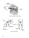
1. Install new Ice Bank Control Bulb Holder (item 6) on evaporator coils as shown in Figure 1.
2. Install O–Ring (item 7) on Ice Bank Control Bulb as shown in Figure 2).
3. Insert end of the Ice Bank Control Bulb in the Ice Bank Control Bulb Holder.
4. Install O–Ring (item 7) on Ice Bank Control Bulb as shown in Figure 2 to secure control bulb in the holder.