


3 569000264
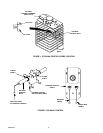
5. Place product coils assembly back in position inside the Unit. Make sure ice bank control capillary tube is
routed from ice bank control bulb up along right front side (facing front of Unit) of the Unit and on up to the
ice bank control as shown in Figure 3.
6. Connect product tubes, connected to the product coils, to backs of the dispensing valves.
7. Place Unit product inlet fittings up through holes in the agitator motor assembly bracket and secure with
white plastic washers and hex nuts.
8. Place the agitator motor assembly bracket back into position on the Unit. Secure agitator motor assembly
bracket with six screws retained in step 12 of PREPARING DISPENSER FOR KIT INSTALLATION.
9. Connect product source product inlet lines to Unit product inlet lines fittings on the agitator motor assembly
bracket.
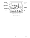
10. Place the new ICE BANK CONTROL (item 1) in approximate mounting position on the agitator motor as-
sembly bracket as shown in Figure 3.
11. Install SNAP BUSHING (item 11) in hole in ICE BANK CONTROL BOX (item 2).
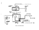
12. Connect BLACK ELECTRICAL WIRE (item 8) and RED ELECTRICAL WIRE (item 9) to terminals on the
ice bank control as shown in Figure 2.
13. Install ICE BANK CONTROL (item 1) inside the ICE BANK CONTROL BOX (item 2) and secure with
SCREWS (item 5).
14. Place ice bank control capillary tube in hole in the key-hole slot in the ice bank control box.
15. Install GROMMET (item 3) on the ice bank control capillary tube, then slide grommet up on the capillary
tube and install in key-hole slot in ice bank control box.
16. Route Unit wiring harness electrical wires in through snap bushing installed in the ice bank control box.
17. Connect Unit wiring harness green ground wire to ground lug inside the control box. Secure ground con-
nection with HEX NUT (item 14).
18. Complete remainder of wiring connections inside the ice bank control box by referring to Figure 4 Wiring
Diagram.
19. Place ice bank control in position on the agitator motor assembly bracket. Secure ice bank control to the
motor assembly bracket with SELF DRILLING SCREWS (item 10).
20. Very carefully, route capillary tube along Unit wiring harness as shown in Figure 3.
21. Using WIRE TIES (item 12), secure capillary tube to the Unit wiring harness as shown in Figure 3.
22. Install LABEL, HAZARD SHOCK (item 4) on ice bank control cover as shown in Figure 3.
23. Install handle on Unit and secure with screws.
RESTORING UNIT OPERATION
1. Fill water tank with water as instructed in manual provided with your Dispenser. USE LOW–MINERAL–
CONTENT WATER WHERE A LOCAL WATER PROBLEM EXIST.
2. The Unit product systems should be sanitized at this time. Refer to manual provided with your Dispenser
for sanitizing instructions.
3. Connect electrical power to the Unit.
4. Connect Unit product inlet lines to product tanks, then open each dispensing valve to bleed air from the
systems and until product is dispensed.
5. Check the Unit for product leaks and repair if evident.
6. Check Unit for proper operation, then close hinged top cover.