


2
620913202
INSTALLATION INSTRUCTIONS
IMPORTANT: It is the responsibility of the Installer to ensure that the water supply to the dispensing
equipment is provided with protection against backflow by an air gap as defined in ANSI/ASME A112
1.2-1979; or an approved vacuum breaker or other such method as proved effective by test.
Water pipe connections directly connected to a potable water supply shall be sized, installed, and
maintained according to Federal, State, and local codes.
All drain connections must be installed with adequate backflow protection to prevent contamination of
the potable water supply and the ice storage hopper in accordance with Federal, State, and local
codes.
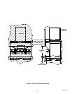
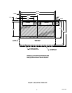
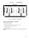
1. Locate the Dispenser indoors on a level countertop. The Dispenser must be sealed to the countertop. Us-
ing the mounting template (see Figure 3), determine the outline of the Dispenser and the six mounting
holes for the desired location of the Dispenser. Remove the (6) plastic hole plugs from the threaded base
mounting holes, the two base black plastic panels, and the two rear stainless steel cabinet access panels.
Apply a continuous bead of NSF International (NSF) listed silastic sealant (Dow Corning 732 or equal)
around the outline of the Dispenser on the countertop. Position the Dispenser on the countertop and wipe
away any excess sealant immediately. Bolt the Dispenser to the countertop with 3/8--16 bolts.
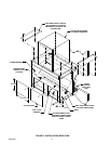
2. The beverage and water manifold inlet lines, ice storage hopper drain tubes (2), and electrical power cord
are routed through the two large openings in the base of the Dispenser. Access for these hook-ups is pro-
vided through the two rear cabinet openings.
3. Connect the (2) hopper drain tubes to an approved drain system with a backflow preventer in compliance
to the local plumbing code. Do not “tee” into the drip tray drain line.
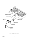
4. DRIP TRAY DRAIN ASSEMBLY: Route the drain tube to an open drain with the end of the tube above the
“flood” level of the drain. Use the tubing, fittings, clamps, and insulation provided with the Dispenser to
assemble the drain. The completed drain line must pitch continuously downward and contain no “traps” or
improper drainage will result.
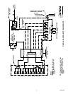
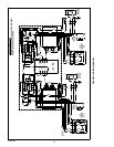
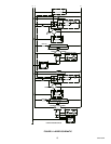
5. BEVERAGE SYSTEM: Connect the beverage system product lines to the Dispenser. Consult the water
manifold hook-up schematic located on the front panel of the Dispenser to determine the connections for
the Dispenser’s internal water manifold for the desired non-carb and carbonated valve positions. These
connections should be performed by a qualified Service Person.
6. Replace the two rear stainless steel cabinet panels after completing the hook-ups. Seal these access pan-
els to the countertop with the approved sealant from step 1.
7. Clean the ice storage hopper interior (see CLEANING INSTRUCTIONS in the Owner’s manual).
8. Connect the power cord to a 120 VAC, 60 Hz 3-wire grounded receptacle.