


IDC Installation Manual
Publication Number: 621057403INS - 4 - © 2005-2008, IMI Cornelius Inc.
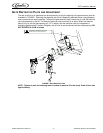
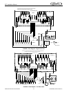
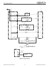
5. Connect the beverage system product tubes as indicated in applicable Flow Diagram FIGURE 4 or
FIGURE 5. This work should be done by a qualified service person.
NOTE: See applicable Flow Diagram (see FIGURE 4 or FIGURE 5) or Decal on the lower front of
the unit for the location of syrup and water connections.
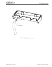
6. Clean the hopper interior (see CLEANING INSTRUCTIONS in Owner’s Manual).
7. Connect the unit power cord to a 120 volt, 60 cycle, 3–wire grounded receptacle. For 220-240 Volt
International Units, a 3-wire power cord is provided. An adapter plug for the particular country will
need to be provided by the Installer.
ADJUST CARBONATOR CO
2
REGULATOR AND TURN WATER INLET SUPPLY
L
INE ON
CAUTION: Before connecting the CO
2
regulator assembly to a CO
2
cylinder, turn the regulator
adjusting screw to the left (counterclockwise) until all tension is relieved from the adjusting screw
spring.
1. Open (counterclockwise) CO
2
cylinder valve slightly to allow lines to slowly fill with gas, then open
the valve fully to back-seat the valve. (Back-seating the valve prevents leakage around the valve
shaft).
2. The carbonator CO
2
regulator is fixed at a nominal 75 psi.
3. Open one of the post-mix dispensing valves to exhaust trapped air inside the carbonator tank.
CAUTION: Never operate the carbonator pump with the water inlet supply line shutoff valve closed.
“Dry running” the water pump will burn out the pump. A pump damaged in this manner is not
covered by warranty.
4. Open the water inlet supply line shutoff valve.
UNIT OPERATION
WARNING: The unit must be electrically grounded to avoid possible fatal electrical shock or serious
injury to the operator. The unit power cord is equipped with a three-prong plug. If a three-hole
(grounded) electrical outlet is not available, use an approved method to ground the unit.
1. Connect electrical power to the Unit.
2. Check for water and CO
2
leaks and tighten any loose connections.
3. Enable the carbonator pump by turning the switch ON. The switch is located on the junction box of
the carbonator pump. The water pump will start and fill the carbonator tank with carbonated water.
The water pump will stop when the carbonator tank is full. The carbonator pump will now cycle on
whenever a drink is dispensed and the liquid level in the carbonator tank drops below the low level
probe (approximately 22 oz).
4. Dispense a drink until the carbonator pump cycles on. The refill time should be about 5 - 7 seconds.
5. If the carbonator pump appears to be short-cycling where the refill time is 1 - 2 seconds, refer to the
Troubleshooting section.