


3
90632
INSTALLATION INSTRUCTIONS
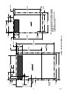
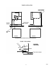
1. The ice dispenser must be fastened and sealed to the counter, using the hardware supplied with the unit.
The template drawings (Figure NO TAG) indicate openings which must be cut in the counter for the ice
feed tube and utilities. Check that the counter mounting surface for the dispenser is level.
Apply a continuous bead of NSF approved silastic sealant (Dow 732 or equal) approximately 1/4” inside of
the unit outline dimensions, and around all openings. Then position the unit on the counter within the out-
line dimensions. Fasten the ice dispenser in place with mounting hardware provided. All excess sealant
must be wiped away immediately.
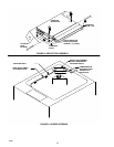
2. Position the icemaker and install the feed tube and other components according to the instruction supplied
with the feed tube kit.
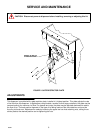
3. Route the icemaker control bulb along the outside of the dispenser cabinet, and into the hopper as shown
in Figure 2. Install insulating tubing and mount the bulb to the deflector assembly as shown in Figure 5.
Use care when handling the bulb to avoid damaging or kinking it. Do not allow the bulb to contact any cold
surfaces, or false sensing will occur. Route the bulb away from electrical terminals, moving parts, or sharp
metal edges.
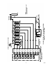
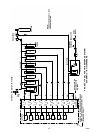
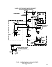
4. Permanently wire the dispenser to a source of 120V, 60Hz. power as shown in Figure 3. Wiring must con-
form to N.E.C. and local codes
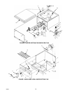
5. On beverage units --AB, and -- ABC connect the beverage system product lines as indicated in Figures 4,
5, and 9. This work should be done by a qualified service person.
6. Connect the drain tube to an open drain. If additional piping is required, it must be 3/4” IPS (or equal) and
must continuously pitch downward away from the unit for proper drainage.
7. Complete the installation of the icemaker according to the instructions supplied with the unit and the mark-
ings on the icemaker itself.
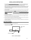
SINK DRAIN ASSEMBLY
1. Use tube, clamp and insulation provided to assemble drain.
2. To assure proper drainage, do not allow “trap” to form in drain line. Be sure drain line runs flat with bottom
of dispenser (see Figure 1)
DISPENSER BOTTOM
DRAIN LINE
FIGURE 1. SINK DRAIN ASSEMBLY