


4
Installation
Important: The installation instructions for cooking
ranges shall include a recommendation that such
appliances should not be placed adjacent to a door
access to minimise the likelihood of persons using
the door making contact with pans on the hob surface.
Important: before making any adjustements, maintenance
etc. to the cooker, first ensure that it is disconnected from
the electricity supply.
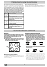
Positioning
The appliance can therefore be installed next to cabinets,
provided the height does not exceed that of the hob.
Important: The hob should never be installed in proximity
of a door access. People opening and closing the door
could come into contact with pots or pans cooking on the
hob.
Levelling Your Appliance (only on certain models)
4 support feet which are adjusted using screws are located
in the lower part of the cooker. These level off the oven
when necessary. It is essential that the cooker be standing
level.
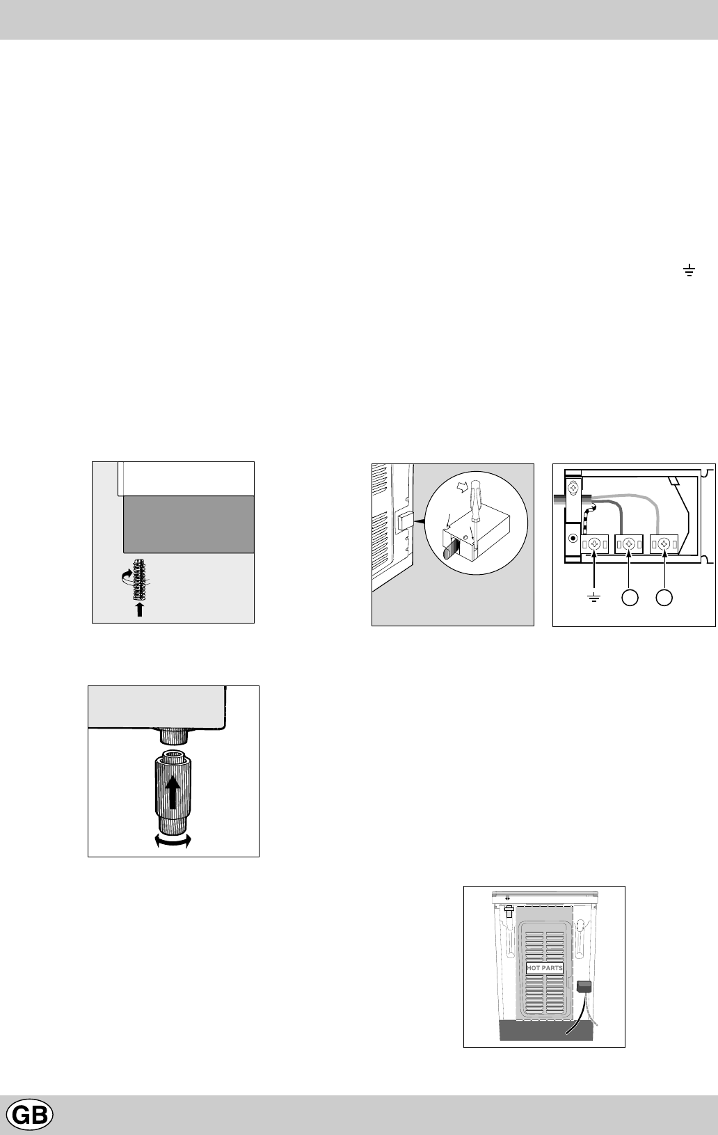
Mounting the legs (only on certain models)
Press-fit legs are supplied which fit under the base of your
cooker.
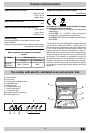
Electrical connection
Electric cookers come without a power supply cable. The
cooker is designed to operate on an electricity supply
which conforms to the electrical data shown on the Rating
Plate. The cooker can be connected to the mains only
after removing the back panel of the cooker itself with a
screwdriver.
N.B.: the following installation procedure must be carried
out by a qualified electrician. The electrical installation must
comply with the IEE Regulations, Building & local By-Lays.
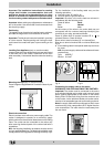
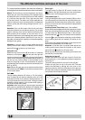
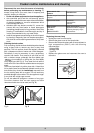
For the installation of the feeding cable carry out the
following operations:
l Unscrew screw “V” (see fig. A)
l Pull and open the junction blok lid
Important: the wires in the mains lead are coloured in
accordance with the following code:
Green & Yellow Earth
Blue Neutral
Brown Live
As the colours of the wires in the mains lead may not
correspond with the coloured markings identifying the
terminals in your plug, proceed as follows:
Green & Yellow wire to terminal marked “E” or or
coloured Green or Green & Yellow.
Brown wire to terminal marked “L” or coloured Red.
Blue wire to terminal marked “N” or coloured Black (see
fig. B).
l fix the feeding cable in the special cable stop and close
the cover.
N.B.: the power supply cable must have these minimum
requirements:
Type: H05RR-F
Section: 3x4 mm
2
4 2
N L
Fig. A Fig. B
Connecting the supply cable to the mains
WARNINGS: THIS APPLIANCE MUST BE EARTHED.
Important: The cooker must be connected to the mains
by a switched (double pole) cooker outlet correctly fused
with a capacity appropriate to that shown on the cooker
Rating Plate. All electrical wiring from the consumer unit
to the cooker, via the switched double pole cooker outlet,
must be of an acceptable type and current rating as above.
Note: the supply cable must be positioned so that it never
reaches at any point a temperature 50°C higher than the
room temperature. The cable must be routed away from
the rear vents.
HOT PARTS