21
Installation Instructions
CONNECTING TO THE GAS SUPPLY
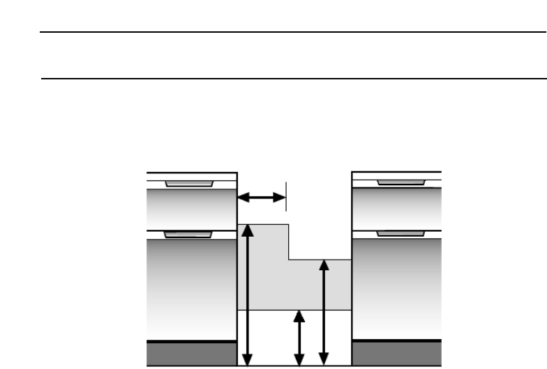
The cooker is designed to match the depth of standard 600mm worktops. An adaptor
backplate should, therefore, be fitted within the shaded area shown to allow the
cooker to be pushed fully to the wall. If a forward facing backplate is used, it must be
chased into the wall.
Connection to the cooker should be made with an approved appliance flexible
connection to BS 669.
A length of 0.9 to 1.25m is recommended. The length of hose chosen should be such
that when the cooker is in situ, the hose does not touch the floor.
The temperature rise of areas at the rear of the cooker that are likely to come in
contact with the flexible hose do not exceed 70˚C.
OPERATIONAL CHECKS
After installation, check for gas soundness. The supply pressure can be checked at the
grill injector. Access to the injector is by first removing the baffle at the front of the grill
fastened by two screws. Then remove the fastening screw on the right hand side of the
burner and slide the burner off the injector. Ensure that the grill burner is correctly
located under the fixing screw on reassembly.
Fit the battery. Fit the hotplate burner bodies, enamelled discs and pan supports.
Referring to the instructions for use where necessary.
1. Check that the hotplate and grill burners ignite correctly and burn with a steady
flame. Check for a steady flame on the low setting.
2. Check that with the oven set to mark 9, the burner ignites at low rate, and then
increases to full rate within 60 seconds.
Leave the oven full on with the door closed for 10 minutes, and check that when
the control is turned to the “S” setting that the flame reduces.
Instruct the user on the operation of the cooker.
250
680
250
500


