10
IE
GB
* At 15°C and 1013 mbar-dry gas
Propane G31 H.s. = 50,37 MJ/kg
Butane G30H.s. = 49,47 MJ/kg
Methane G20 H.s. = 37,78 MJ/m
3
TECHNICAL SPECIFICATIONS
ENERGY LABEL
Directive 2002/40/EC on the label of electric ovens
Norm EN 50304
Energy consumption for Natural convection
heating mode: Convection
Declared energy consumption for Forced convection Class
heating mode: Fan assisted (mod. KP 59 MS)
This appliance conforms with the following European Economic
Community directives:
- 73/23/EEC of 19/02/73 (Low Voltage) and subsequent modifications;
- 89/336/EEC of 03/05/89 (Electromagnetic Compatibility) and
subsequent modifications;
- 90/396/EEC of 29/06/90 (Gas) and subsequent modifications;
- 93/68/EEC of 22/07/93 and subsequent modifications.
Oven accessories which may come into contact with food
are make in materials complying to what is laid down in
EEC Directive 89/109 of 21.12.88 and national regulations
in force.
BURNERS AND NOZZLES SPECIFICATIONS
must be fitted between the appliance and the mains supply
outlet. The yellow-green earth wire must not be interrupted
by the switch. The supply cable must be in such a position
that no part of it can reach a temperature of 50 °C above
room temperature. Do not use adapters or shunts as they
could cause heating or burning. Before connecting to the
power supply, make sure that:
• the limiter valve and the domestic system can withstand
the load from the appliance (see rating plate);
• the supply system is efficiently earthed according to
standards and laws in force;
• the socket or double-pole switch are easily accessible when
the appliance is installed.
FAILURE TO OBSERVE THE ACCIDENT-PREVENTION
REGULATIONS RELIEVES THE MANUFACTURER OF ALL
LIABILITY.
ELECTRICAL CONNECTION
Important: the wires in the mains lead are coloured in
accordance with the following code:
Green & Yellow - Earth
Blue - Neutral
Brown - Live
As the colours of the wires in the mains lead may not
correspond with the coloured markings identifying the
terminals in your plug, proceed as follows:
Connect the Green & Yellow wire to terminal marked “E” or
or coloured Green or Green & Yellow.
Connect the Brown wire to the terminal marked “L” or coloured
Red.
Connect the Blue wire to the terminal marked “N” or coloured
Black.
Replacing the cable
Use a rubber cable of the type H05VV-F with a suitable cross
section 3 x 1.5 mm².
The yellow-green earth wire must be 2-3 cm longer than the
other wires.
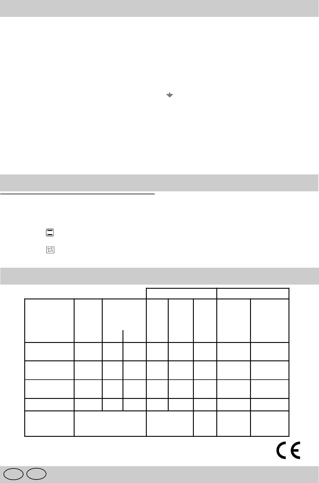
Table 1 Liquid Gas Natural Gas
Burner Diameter
(mm)
Thermal Power
kW (p.c.s.*)
By-pa-
ss
1/100
(mm)
Nozzle
1/100
Flow*
g/h
Nozzler
1/100
Flow*
l/h
Nom. Red. (mm) G30/31 (mm)
Fast
(Large) (R)
100 3.00 0.7 40 86 218 116 286
Semi Fast
(Medium) (S)
75 1.65 0.4 30 64 120 96 157
Auxiliary
(Small) (A)
55 1.00 0.4 30 50 73 71 95
Triple Crown (TC) 130 3.25 1.3 57 91 236 124 309
Supply pressures Nominal (mbar)
Minimum (mbar)
Maximum (mbar)
28-30
20
35
20
17
25


