


Installing and Replacing Desktop Board Components
47
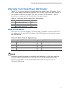
Alternate Front Panel Power LED Header
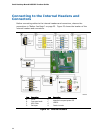
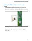
Figure 23, F shows the location of the alternate front panel power LED header. Pins 1
and 3 of this header duplicate the signals on pins 2 and 4 of the front panel header. If
your chassis has a three-pin power LED cable, connect it to this header. Table 9
shows
the pin assignments for the alternate front panel header.
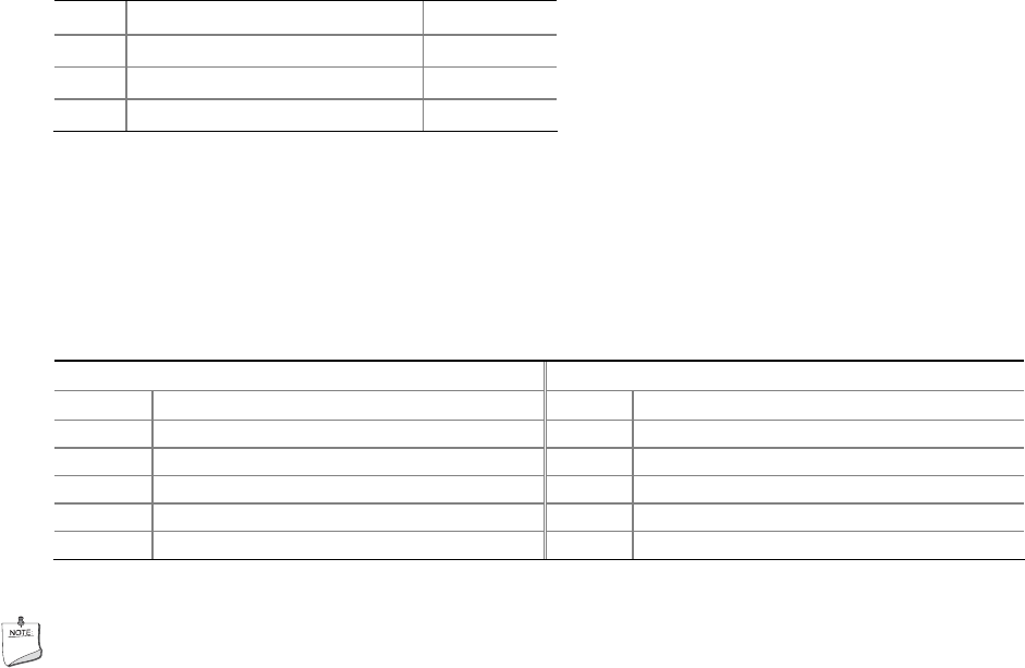
Table 9. Alternate Front Panel Power LED Header
Pin Description In/Out
1 Front panel green LED Out
2 No pin
3 Front panel yellow LED Out
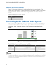
USB 2.0 Headers
See Figure 23, G for the location of the three USB 2.0 headers. Table 10 shows the
pin assignments for each USB 2.0 header. Each USB header can be used to connect
two USB devices.
Table 10. USB 2.0 Header Signal Names
USB Port A USB Port B
Pin Signal Name Pin Signal Name
1 Power (+5 V) 2 Power (+5 V)
3 D- 4 D-
5 D+ 6 D+
7 Ground 8 Ground
9 Key 10 No Connection
Note: USB ports may be assigned as needed.
NOTE
Computer systems that have an unshielded cable attached to a USB port might not
meet FCC Class B requirements, even if no device or a low-speed USB device is
attached to the cable. Use a shielded cable that meets the requirements for a
full-speed USB device.