


Intel Desktop Board DG35EC Product Guide
48
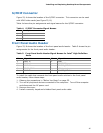
Chassis Intrusion Header
Figure 23, H on page 44 shows the location of the chassis intrusion header. This
header can be connected to a mechanical switch on the chassis to detect if the chassis
cover is removed. Table 11 shows the pin assignments
for the chassis intrusion
header.
Table 11. Chassis Intrusion Header
Pin Description
1 Intruder
2 Ground
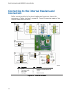
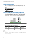
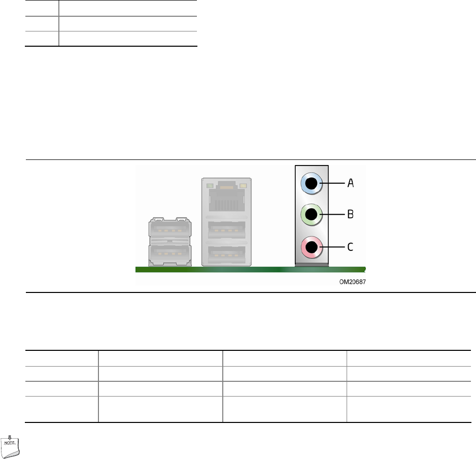
Connecting to the Onboard Audio System
After installing the RealTek audio driver from the Intel Express Installer CD-ROM, the
multi-channel audio feature can be enabled. Figure 24 shows the back panel audio
connectors
. Table 12 lists the functions of the connectors
in the different audio
modes.
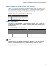
Figure 24. Back Panel Audio Connectors
Table 12. Back Panel Audio Connector Definition
Connector 2-Channel Function 4-Channel Function 6-Channel Function
A (Blue) Line in Left/right rear Left/right rear
B (Green) Line out Left/right front Left/right front
C (Pink) Mic in Mic in Subwoofer/center
channel
NOTE
The back panel line out connector is designed to power either headphones or amplified
speakers only. Poor audio quality may occur if passive (non-amplified) speakers are
connected to this output.