31
SECTION 6: ASSEMBLY PARTS
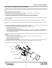
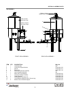
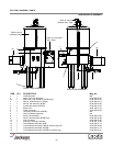
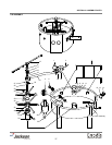
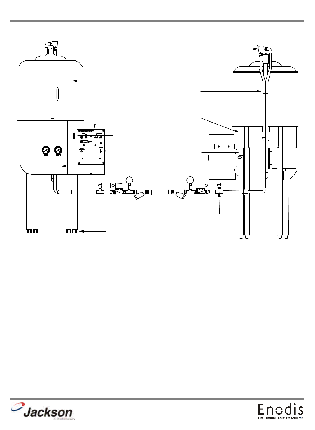
10A ASSEMBLY
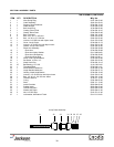
ITEM QTY DESCRIPTION Mfg. No.
1 1 Hood Assembly N/A
2 1 Control Box Support Bracket 5700-000-24-76
3 1 Shroud 5700-000-24-77
4 4 Bullet Feet 5340-108-01-03
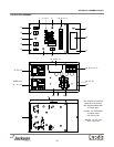
5 1 Complete Control Box Assembly N/A
6 1 Vacuum Breaker Assembly N/A
7 1 Motor and Pump Assembly 5700-002-60-91
8 1 Incoming Plumbing Assembly 5700-002-60-98
9 1 Outlet Connector 5700-002-61-19
10 1 Tub Weldment Assembly 10A 5700-002-60-95
10 1 Tub Weldment Assembly 10A (9” Shorter Leg) 5700-002-62-00
11 2 Bracket, Vacuum Breaker Support 5700-000-32-27
7
Refer to Vacuum
Breaker Assy. Page
11
10
9
2
Refer to Control
Box Assy. Page
Refer to Hood
Assembly Page
3
4
8
REAR VIEW ASSEMBLYFRONT VIEW ASSEMBLY


