


It is also recommended that a shock absorber (not supplied) be installed in the incoming water line. This prevents line hammer
(hydraulic shock), induced by the solenoid valve as it operates, from causing damage to the equipment.
STEAM LINE CONNECTIONS: Some machines covered in this manual are designed to use low pressure steam as a source
of heat for wash tank water. The machines come with lines by which outside source steam needs to be connected. Connect all
incoming steam lines in accordance with the steam booster manufacturer’s instructions. Ensure that all applicable codes and
regulations are adhered to. See machine data plate for information concerning steam flow pressure.
GAS CONNECTIONS: Some machines covered in this manual are designed to use gas as an outside source of heat for wash
tank water. The machines come with connections by which an outside source needs to be connected. Connect all incoming gas
lines in accordance with the gas booster manufacturer’s instructions. Ensure that all applicable codes and regulations are
adhered to.
PLUMBING CHECK: Slowly turn on the water supply to the machine after the incoming fill line and the drain line have been
installed. Check for any leaks and repair as required. All leaks must be repaired prior to placing the machine in operation.
ELECTRICAL POWER CONNECTION: Electrical and grounding connections must comply with the applicable portions of the
National Electrical Code ANSI/NFPA 70 (latest edition) and/or other electrical codes.
Disconnect electrical power supply and place a tag at the disconnect switch to indicate that you are working on the
circuit.
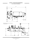
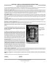
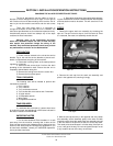
The dishmachine data plate is located on the right side and to
the front of the machine. Refer to the data plate for machine
operating requirements, machine voltage, total amperage load
and serial number.
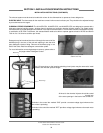
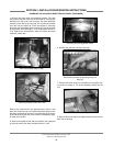
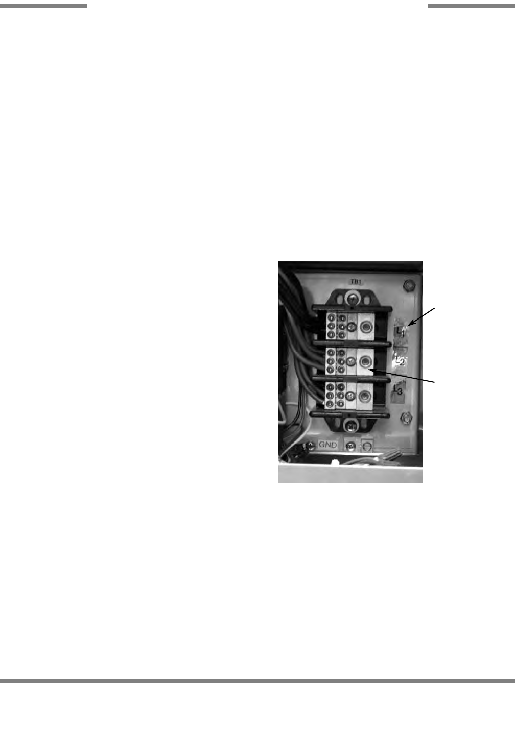
To install the incoming power lines, open the control box. Install
conduit into the pre-punched holes in the back of the control box.
Route power wires and connect to power block and grounding
lug. Install the service wires (L1, L2, and L3 (3 phase only)) to
the appropriate terminals as they are marked on the terminal
block. Install the grounding wire into the lug provided. Tighten
the connections. It is recommended that “DE-OX” or another
similar anti-oxidation agent be used on all power connections.
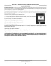
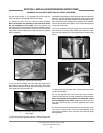
VOLTAGE CHECK: Ensure that the power switch is in the OFF
position and apply power to the dishmachine. Check the incom-
ing power at the terminal block and ensure it corresponds to the
voltage listed on the data plate. If not, contact a qualified service
agency to examine the problem. Do not run the dishmachine if
the voltage is too high or too low. Shut off the service breaker
and mark it as being for the dishmachine. Advise all proper per-
sonnel of any problems and of the location of the service break-
er. Replace the control box cover and tighten down the screws.
VENTILATION OF DISHMACHINE: The dishmachine should be located with provisions for venting into an adequate exhaust
hood or ventilation system. This is essential to permit efficient removal of the condensation exhaust. Ensure that the exhaust
system is acceptable in accordance with all applicable codes and standards.
NOTE: Any damage that is caused by steam or moisture due to improper ventilation is NOT covered under the war-
ranty.
This units covered in this manual have the following exhaust requirements:
Load End: 200 CFM
Unload End: 400 CFM
AJ-44C Series Technical Manual 7610-001-76-22
Issued: 03-21-2006 Revised: N/A
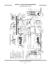
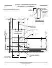
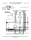
SECTION 2: INSTALLATION/OPERATION INSTRUCTIONS
INSTALLATION INSTRUCTIONS (CONTINUED)
31
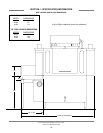
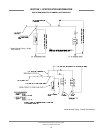
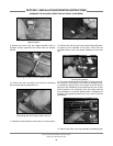
Incoming Power Connection
Decal showing
“L1”, “L2”, & “L3”
(3 phase models
only).
Terminal Block