


26
PageCreated:05‐04‐2010
Revised:02‐25‐2011
Technical Manual (07610-003-78-18)
TROUBLESHOOTING
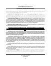
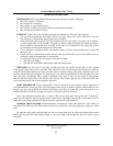
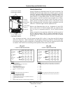
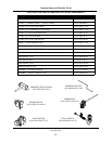
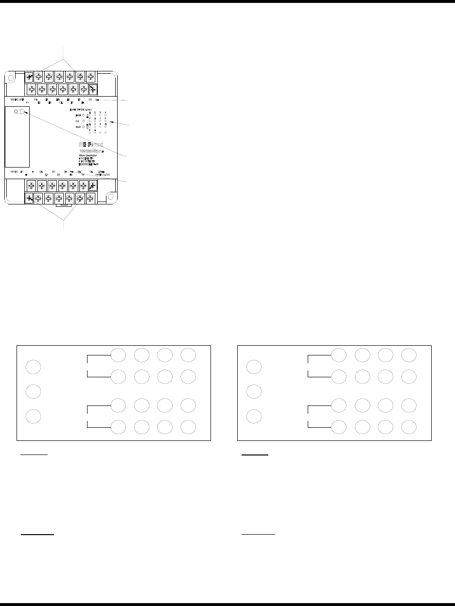
Green LED lights are illuminated on the PLC when in operation. The
POWER, OK & RUN lights indicate that 24VDC power is available
to the PLC and that is functioning properly. If the RUN light is out,
first check that the RUN toggle switch located behind the snap cover
panel of the PLC is in the RUN position. Less likely is that the opera-
tional program of the PLC may have been corrupted or lost. Tempo-
rary power surges may have occurred. Secure all power to the ma-
chine, wait for 30 seconds and restore power. Verify that the Green
light is illuminated to the 24vdc power supply immediately to the left
of the PLC. If the RUN light is still off, replace the PLC.
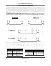
Refer to the illustration below for the designation of each LED.
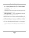
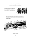
PLC1 is used for the 44” Electric & Steam units. An expansion PLC
(PLC2) is used in conjunction with PLC1 for 66” Electric & Steam
units.
Inputs correspond to the connections behind the top flip up panel of
the PLC and are marked I1 thru I8. Outputs correspond to the con-
nections behind the bottom flip up panel of the PLC and are marked
Q1 thru Q8.
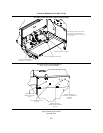
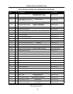
Note: All outputs are fused. Q1 & Q2 outputs for both PLC’s utilize 1.0 Amp fuses and Q3-Q8 outputs
utilize 0.75 Amp fuses. When illuminated , the LED lights on the front of each PLC will show the input
from and the outputs to various components as illustrated below. LED’s that may illuminate on PLC2 that
are marked “NOT USED” have no bearing on the operation of the current ware-washers.
1234
5678
INPUTS
1 234
5678
OUTPUTS
PWR
RUN
OK
PLC1
LIGHT CONFIGURATION
1234
5678
INPUTS
1 234
5678
OUTPUTS
PWR
RUN
OK
PLC2
LIGHT CONFIGURATION
UTILIZE THESE SCREWS
FOR PLC REPLACEMENT
UTILIZE THESE SCREWS
FOR PLC REPLACEMEN
T
STATUS
INDICATING
LIGHTS
INPUTS
OUTPUTS
RUN TOGGLE
SWITCH
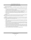
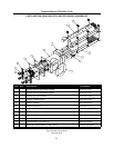
INPUTS:
1. ON/OFF SWITCH
2. DOOR SWITCH SAFETY INTERLOCKS
3. RACK INLET SWITCH
4. FINAL RINSE SWITCH
5. LOWER WASH FLOAT SWITCH
6. UPPER WASH FLOAT SWITCH
7. MANUAL / DELIME SWITCH
8. N/A
OUTPUTS:
1. RINSE SOLENOID / RINSE SIGNAL RELAY
2. WASH TANK FILL SOLENOID
3. DRIVE MOTOR CONTACTOR
4. WASH MOTOR CONTACTOR
5. WASH HEATER CONTACTOR or STEAM HEAT RELAY
6. VENTILATION FAN RELAY
7. N/A
8. SIDE-LOADER SWITCH (ON WITH NO RACK PRESENT)
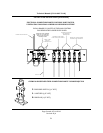
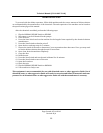
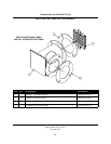
INPUTS:
1. LOWER PRE-WASH FLOAT SWITCH (66 UNITS ONLY)
2. UPPER PRE-WASH FLOAT SWITCH (66 UNITS ONLY)
3. N/A
4. N/A
5. N/A
6. N/A
7. N/A
8. N/A
OUTPUTS:
1. PRE-WASH TANK FILL SOLENOID (66 UNITS ONLY)
2. PRE-WASH MOTOR CONTACTOR (66 UNITS ONLY)
3. N/A
4. N/A
5. N/A
6. N/A
7. N/A
8. N/A