7
SECTION 2: INSTALLATION & OPERATION INSTRUCTIONS
INSTALLATION INSTRUCTIONS (CONTINUED)
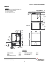
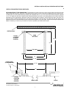
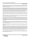
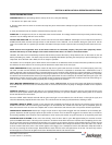
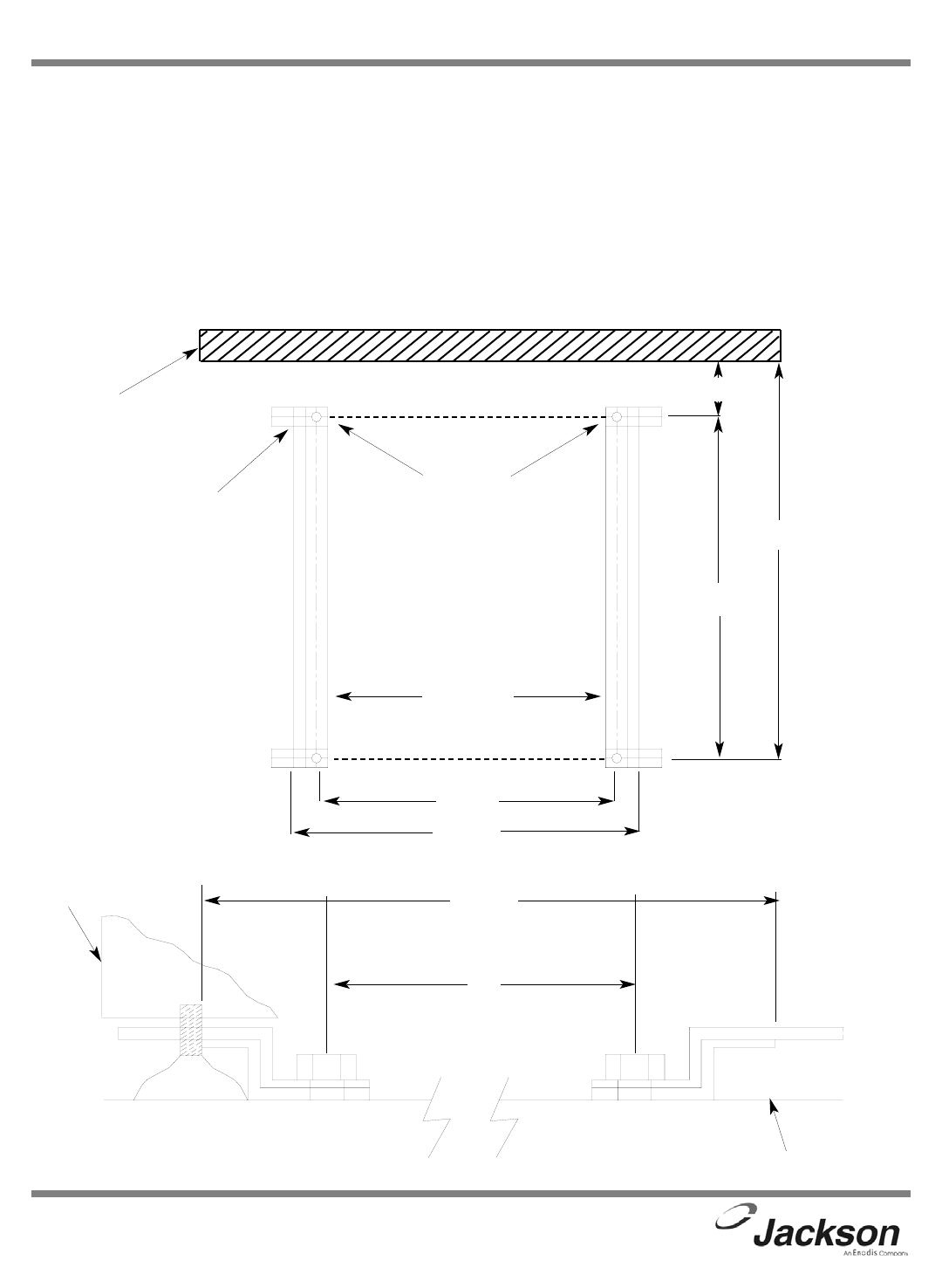
DECK MOUNTING OF THE DISHMACHINE: The dishmachine must be secured in place using the deck mounting tracks and
caps provided with machine. Install the (4) adjustable feet provided into screw holes where shipping bolts were removed earli-
er. Adjust the level of the dishmachine by screwing the adjustable feet in or out. The front of the machine should be adjusted
1/4” to 1/2” higher than the back. Install the deck mounting hardware as shown in the drawing below, at the location where the
dishmachine will be permanently positioned. Install 3/8” stainless steel lug bolts to secure tracks and caps to the deck. Drill
holes into deck as shown below and insure rear holes are located 2-1/4” from the wall. The racks and rear end caps may be
tightened at this time. Slide dishmachine onto tracks and into position at rear end caps. Install front end caps into place and
adjust if necessary to remove any movement of machine; if possible, tack weld tracks to deck.
JPX-300NSU Technical Manual
7610-002-75-96 Rev. E (08/16/2005))
TYPICAL
LOCATION
OF FOOT
LEVELER
EXISTING WALL
19”
21 7/8”
21 1/4”
23 1/2”
2 1/4”
TOP VIEW
REAR
END CAPS
FRONT VIEW
19”
TYPICAL
LOCATION
OF FOOT
LEVELER
FRONT PANEL
OF DISHWASHER
21 7/8”
FLOOR


