


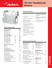
TS-66 Traditional
Series
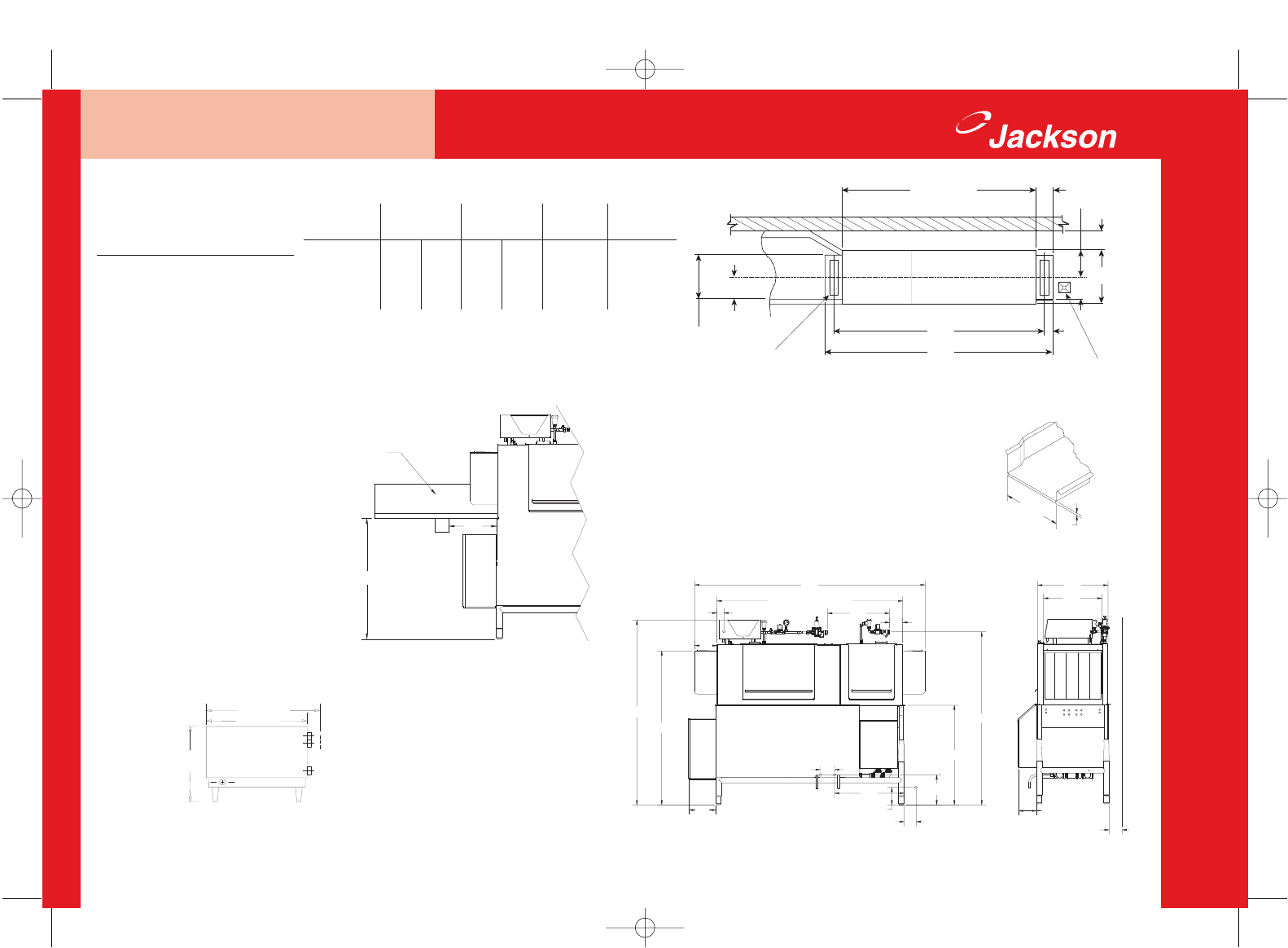
Right to Left Operation Shown
07610-002-97-65A 8/04
All specifications subject to change without notice.
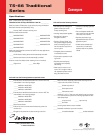
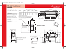
Recommended Table Fabrication
66”
TABLE TO TABLE
8”
12-1/2”
4”
74”
82”
4”
Floor sink or drain with
3” minimum drain line.
26”
8”
10-1/2”
21”
OPENING
4” wide x 16” long cutout in vent
cowl/splash shield. Shipped with
cover plates.
1-PH 3-PH 1-PH 3-PH *3-PH
208 Volts 60 Cycles 88.3 51.8 18.3 10.1 66.6
230 Volts 60 Cycles 81.5 47.8 18.3 10.1 60.2
460 Volts 60 Cycles N/A 23.9 N/A 5.1 30.1
TS-66 Series
Electrical Data
Approximate Total Load Amps
Electric Tank Heat Steam Tank Heat Optional 24 KW
Models: Models: Electric
TS-66 TS-66S Booster Heater
Optional 36 KW
Electric
Booster Heater
*3-PH
99.9
90.4
45.2
* Option electric boosters come in 3 phase only.
Note: Optional booster heater requires separate electrical connection. 24
KW and 36 KW booster heaters are designed to supply the dishmachine
with rinse water at the appropriate temperature. Models do NOT come
with booster heaters as standard equipment.
30-1/2”
24”
18”
The maximum recommended distance between any electric
booster heater and the dishmachine is 20 ft.
All specifications subject to change without notice.
25”
21”
5-3/4”
WALL
4”
61-1/4”
34”
11-
4-1/2”
6-1/2”
24”
10”
53”
66”
8”
3”
66” TABLE TO TABLE
82”
22”
5”
5”
20-1/2”
1”
10” high backsplash
14”
34”
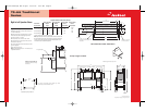
Scrap trough location MUST be a
minimum of 14” from the tub,
regardless of which side the trough
is mounted on.
Scrap Trough Location
Machine height with doors open is 72”.
Drive
Motor
Cover
Legend to Drawing
A– Machine water inlet 1/2” I.P.S., 180°F minimum, 61-
1/4” above finished floor
B– Electrical connection, approximately 61-1/4” above
finished floor. See table for amperage requirements
C– Drain connection-1 1/2” I.P.S.
D– Prewash water inlet 1/2” I.P.S. 110°F-140°F
*E–Condensate return connection, 3/4” FPT (return to
boiler feeder or open drain)
*F– Incoming low pressure steam connection, 3/4” FPT
(gate valve supplied)
*Steam tank heat option only
Note: All vertical dimensions are +/- 1/2” from floor due
to adjustable bullet feet
A
D
C
E
F
B
TS-66 Drawings Rev A.qxd 10/15/04 9:52 AM Page 2