


9
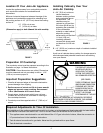
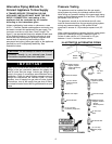
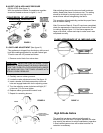
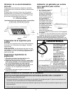
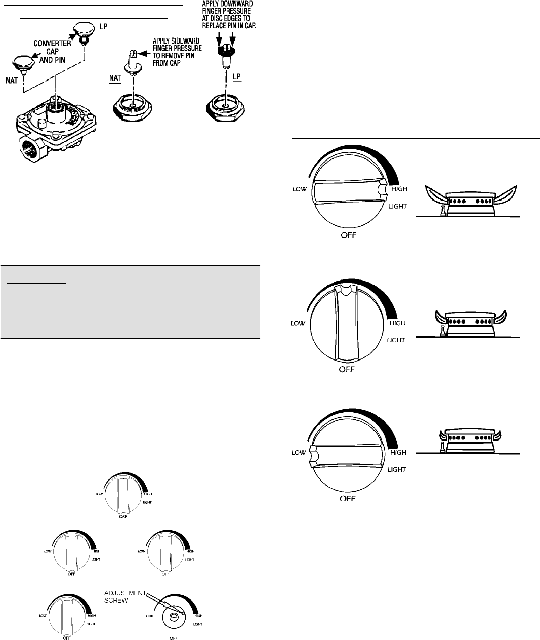
B. INVERT CAP IN APPLIANCE PRESSURE
REGULATOR (See figure 11)
With the appliance installed, the appliance regulator
should be located as shown in figure 3, 4 or 5.
FIGURE 11
CONVERSION OF APPLIANCE
PRESSURE REGULATOR
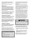
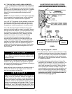
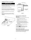
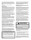
C. LOW FLAME ADJUSTMENT (See figure 12)
This appliance is shipped from the factory with low and
high flame settings adjusted for use with natural gas.
To set for use with LP proceed as follows:
1. Remove control knob from valve stem.
CAUTION: NEVER USE A METAL BLADE TO PRY
KNOB OFF. IF KNOB CANNOT BE EASILY REMOVED,
TUCK THE FOLDS OF A CLOTH DISHTOWEL UNDER
THE KNOB AND PULL THE TOWEL UPWARD WITH
STEADY, EVEN PRESSURE.
2. Carefully remove rubber grommet.
3. Locate the valve adjustment screw. See figure 12.
4. Insert a slender, thin-blade screwdriver into knob
hole and engage blade with slot in adjusting screw .
5. Turn the adjusting screw clockwise until tight (5-7
in-lbs max.). Do not over tighten.
6. Replace rubber grommet and control knob.
7. Repeat for remaining burners.
FIGURE 12
KNOB
KNOB HOLE
(KNOB AND GROMMET
REMOVED)
After adjusting the screw the burner should produce a
stable, steady blue flame of minimum size. The setting
should be checked by turning knob from high to low
several times without extinguishing the flame.
This operation will automatically provide the proper flame
size at medium setting.
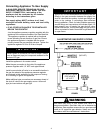
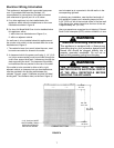
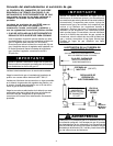
After Conversion Steps A, B and C have been completed,
check the appearance of each burner flame at the Hi and
Lo settings against figure 13. If the flames appear too
large or too small, review each step to make sure it was
completed correctly.
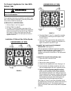
FIGURE 13
FLAME APPEARANCE AT HI, MED AND LOW
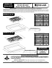
High Altitude Notice
The specified gas burner ratings typically apply to
elevations up to 2000 feet. For higher altitudes, the rates
may need to be reduced to achieve satisfactory operation.
A local certified gas servicer will be able to advise if a
reduction is necessary.