


6
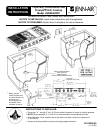
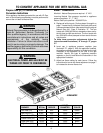
Important Installation Suggestions
1. Chamfer all exposed edges of decorative l aminate to
prevent damage from chipping.
2. Radius corners of cutout and file to insure smooth
edges and prevent corner cracking.
3. Rough edges, inside corners which have not been
rounded and forced fits can contribute to cracking of the
countertop laminate.
4. Countertop must be s upported within 3² of cutout.
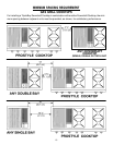
On any bur ner, closing the air shutter too far will
cause the flame to become soft and yellow tipped.
Opening the a ir shutter too wide will c ause the flame
to blow away from the burner ports. Proper adjustment
will produce a sharp, clearly defined, even blue flame.
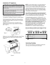
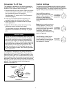
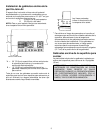
Low Flame Adjustment
(See Illustration “C”)
This appliance i s shipped from the factory with low and
medium flame settings adjusted for use with Natural Gas.
If further adjustment is necessary, or to re-adjust for use
with LP, proceed as follows:
1. Light burner and set control knob for low flame.
2. Remove c ontrol knob from valve stem.
CAUTION: NEVER USE A METAL BLADE TO PRY
KNOB OFF. IF KNOB CANNOT BE EASILY
REMOVED, TUCK THE FOLDS OF A C LOTH
DISHTOWEL UNDER THE KNOB AND PULL THE
TOW EL UPWARD WITH STEADY, EVEN PRES-
SURE.
3. Insert a slender, thin-blade screwdriver into the r ecess
at center of valve s tem and engage blade with slot in
adjusting screw.
4. Turn center stem adjusting screw to set flame size.
...clockwisetoreduce.
...counterclockwise to increase.
5. Replace control knob when adjustment is completed.
Proper adjustment will produce a stable, steady blue flame
of minimum size. The final adjus tment should b e checked
by turning knob from high to low several times without
extinguishing the flame.
This adjustment, at low setting, will automatically provide
the proper flame size at medium setting.
Pressure Testing
The maximum gas supply pressure for the appliance
pressure regulator supplied on this appliance is 1 4² W.C.
The test pressure for c hecking this applianc e pressure
regulator must be at least 6² W.C. for Natural Gas, and at
least 11² W.C. for LP. It is shipped from the factory set for
Natural Gas at 5 ² W.C.
This appliance and its individual shutoff valve m ust be
disconnected from the gas supply piping system during
any pressure testing of that system at test pressures in
excess of 1/2² PSIG (3.5 k Pa).
This appliance must be isolated from the gas supply
piping system by closing its individual manual shutoff
valve during any pressure testing of the gas supply piping
system at test pressures equal to or less than 1/2² PSIG
(3.5 k Pa).
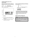
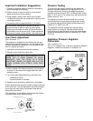
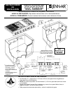
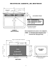
Appliance Pressure Regulator
Conversion
(See Illustration “D”)
This unit is supplied with a Maxitrol Appliance Pressure
Regulator. Follow the instructions in illustration “ D”.
Illustration “D”
NAT
LP
CONVERTER
CAP
AND PIN
MAXITROL APPLIANCE PRESSURE REGULATOR
NAT LP
APPLY
SIDEWARD
FINGER
PRESSURE TO
REMOVE PIN
FROM CAP
APPLY DOWNWARD
FINGER PRESSURE
AT DISC EDGES TO
REPLACE PIN IN CAP
Illustration “C”