


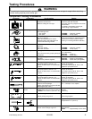
Testing Procedures
!
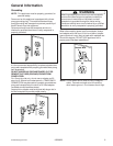
WARNING
To avoid risk of electrical shock, personal injury or death; disconnect power and gas to range before servicing,
unless testing requires power and/or gas.
© 2006 Maytag Services 16026923 15
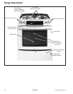
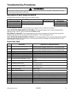
Component Testing Procedures
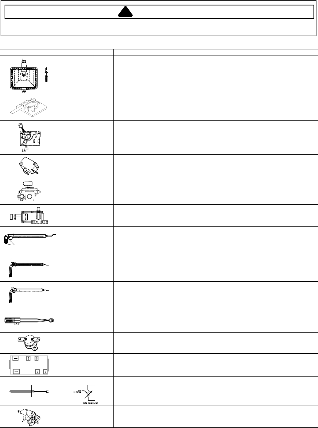
Illustration Component Test Procedure Results
Oven light & housing Disconnect connector and test
resistance of terminals .............................
Measure voltage at oven light...................
Verify bulb is properly inserted.
Continuity with bulb inserted.
120 VAC, see wiring diagram for terminal
identification.
If voltage is not present at oven light,
check wiring or light switches.
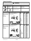
Door plunger switch Remove switch from unit and measure
the following points:
Door closed...........................................
Door open.............................................
COM-NO: .....Continuity (closed).
COM-NO: .....Infinity (open).
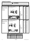
Autolatch assembly Disconnect wires and test for continuity
per wiring diagram....................................
Refer to Parts Manual for correct
autolatch switch associated with the
correct manufacturing number.
See wiring diagram for schematic layout.
Common is in neutral position unless
locking or unlocking autolatch assembly.
C
O
M
N
O
Door lock switch Switch connection in the following
positions:
Door latch locked......................................
Door latch unlocked..................................
COM-NO: .....Continuity (closed).
COM-NO: .....Infinity (open).
Pressure regulator Verify gas pressure (W.C.P.)....................
If on LP service verify proper gas supply
conversion.
5" Natural.
10" LP/propane.
Gas ON: .......Switch up.
Gas OFF: .....Switch down.
Oven valve Verify gas supply is turned on at
regulator...................................................
Attached to pressure regulator.
Gas ON: .......Switch up (at regulator).
Gas OFF: .....Switch down (at regulator).
Broil burner Verify gas is supplied.
Orifice adjusted for Natural or LP .............
Check for obstructions or contamination
in ports .....................................................
Factory set to Natural Gas.
Adjust as necessary.
Air shutter opening set to .281 to .343.
Replace if punctured or torn.
JGS9900BD*
Bake burner Verify gas is supplied.
Orifice adjusted for Natural or LP .............
Check for obstructions or contamination
in ports .....................................................
Factory set to Natural Gas.
Adjust as necessary.
Air shutter opening set to .281 to .343.
Replace if punctured or torn.
Bake burner Verify gas is supplied.
Orifice adjusted for Natural or LP .............
Check for obstructions or contamination
in ports .....................................................
Factory set to Natural Gas.
Adjust as necessary.
Air shutter opening set to .469 to .531.
Replace if punctured or torn.
Ignitor Test for voltage at terminals .....................
Test for circuit amperage..........................
(Ignitor may glow but not have sufficient
amperage to open valve.)
120 VAC.
3.2 - 3.6 Amps. If not, replace.
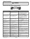
Hi-limit temperature
switch
Normally closed, verify operation:
Open: 249° to 271° F (121° to 133° C)...
Closed: 173° to 207° F (78° to 97° C) ....
Infinite.
Continuity.
L
AB
A1
B1N
Spark module 4 + 0 Test for voltage at terminals L and N........
Check polarity and ground........................
120 VAC.
See wiring diagram.
Temperature sensor
Measure resistance.................................. Approximately 1000 at room
temperature 75° F (23.8° C).
Cooling fan motor Measure voltage.......................................
Check motor windings to ground ..............
120 VAC.
No continuity.
RPM: ............Approximately 1670 to 2070.