26 16026923 © 2006 Maytag Services
Disassembly Procedures
To avoid risk of electrical shock, personal injury or
death; disconnect power and gas before servicing,
unless testing requires power and/or gas.
Cooling Fan Replacement
1. Remove power from unit.
2. Remove range from installation position, see
"Removing and Replacing Range" procedure.
3. Remove back panel, see "Back Panel Removal"
procedure.
4. Label and disconnect wire terminals from cooling fan.
5. Remove screws securing fan to range chassis.
6. Reverse procedure to reinstall cooling fan.
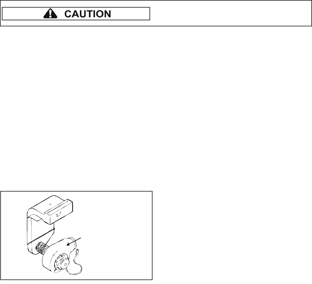
Downdraft Blower Motor Removal
(Select Models)
1. Remove power from unit.
2. Remove bottom access panel, see "Bottom Access
Panel Removal" procedure.
3. Disconnect ducting to allow for downdraft blower
motor removal.
4. Label and disconnect wire terminals.
5. Remove screws securing motor assembly.
6. Reverse procedure to reinstall downdraft blower
motor (select models).
Downdraft
blower motor
assembly
Convection Motor Removal (Select Models)
1. Remove power from unit.
2. Open oven door and remove rack(s).
3. Remove screws securing convection element and fan
cover (on rear wall of oven cavity).
4. Remove screw securing fan blade to fan motor shaft.
5. Remove screws securing fan motor to cavity wall.
6. Slide motor into oven cavity.
7. Label and disconnect wire terminals from motor.
8. Reverse procedure to reinstall convection motor.
Convection Element Replacement
(Select Models)
1. Remove power from unit.
2. Open oven door and remove rack(s).
3. Remove screws securing convection element and fan
cover (on rear wall of oven cavity).
4. Remove screw securing convection element to rear
oven cavity wall.
5. Label and disconnect wire terminals from element.
6. Reverse procedure to reinstall convection element.
Bake Burner and Ignitor Removal
1. Turn off electrical power and gas to the range.
2. Disconnect gas and power from unit.
3. Remove oven door, racks and oven bottom.
4. Remove screws securing bottom bake cover.
5. Raise the back of the bake burner cover and slide
cover back to release the front edge of cover and lift
out of oven cavity.
6. Remove screws securing bake burner assembly to
the oven chassis.
7. Maneuver bake burner from the burner orifice and out
of the slotted location.
8. Pull forward on assembly to allow the ignitor terminal
plug to pass through the back of the oven cavity.
9. Disconnect terminal plug and remove assembly from
the oven cavity.
10.Remove screws securing ignitor to bake burner.
11.Replace and reassemble in reverse order.
Broil Burner and Ignitor Removal
1. Turn off electrical power and gas to the range.
2. Disconnect gas and power from unit.
3. Remove oven door and racks.
4. Remove screws securing ignitor wire plate cover to
back of the oven cavity.
5. Maneuver ignitor wire terminal plug through the rear
of the oven cavity.
6. Disconnect ignitor wire terminal plug.
7. Remove screws securing broiler to oven cavity.
8. Carefully maneuver burner off of the broiler orifice
spud and remove from cavity.
9. Remove screws securing ignitor to broiler.
10.Remove wing nut securing flame spreader to broiler.
11.Replace and reassemble in reverse order.
Oven Sensor Replacement
1. Remove power from unit.
2. Open oven door and remove screws securing sensor
to oven cavity.
NOTE: Gently pull wiring through cavity wall.
3. Label and disconnect wire terminals.
4. Reverse procedure to reinstall sensor.
NOTE: Verify sensor wires are pushed through the
insulation.


