


12
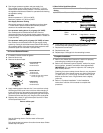
3. Test the gas pressure regulator and gas supply line.
The regulator must be checked at a minimum 1" (2.5 cm)
water column above the set pressure. The inlet pressure to
the regulator should be as follows for operation and checking
the regulator setting:
LP Gas:
Minimum pressure 11" (27.9 cm) WCP
Maximum pressure 14" (35.5 cm) WCP
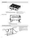
Gas Supply Pressure Testing
Gas supply pressure for testing regulator must be at least
1" water column pressure above the manifold pressure
shown on the model/serial rating plate.
Line pressure testing above ½ psi gauge (14" WCP)
The cooktop and its individual shutoff valve must be
disconnected from the gas supply piping system during any
pressure testing of that system at test pressures in excess of
½ psi (3.5 kPa).
Line pressure testing at ½ psi gauge (14" WCP) or lower
The cooktop must be isolated from the gas supply piping
system by closing its individual manual shutoff valve during
any pressure testing of the gas supply piping system at test
pressures equal to or less than ½ psi (3.5 kPa).
To Convert Surface Burners
1. If installed, remove the burner grates.
2. Remove burner cap.
3. Remove the burner base.
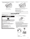
4. Apply masking tape to the end of a 7 mm nut driver to help
hold the gas orifice spud in the nut driver while changing it.
Insert nut driver into gas opening and press down onto the
gas orifice spud and remove by turning the gas orifice spud
counterclockwise and lifting out. Set gas orifice spud aside.
5. Replace with correct LP gas orifice spud. See the “LP Gas
Orifice Spud/Hood Chart.”
Use the following chart to find the exact orifice spud
placement.
Fully insert choke into bottom of medium burner base. Choke
should snap into place.
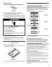
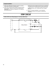
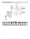
LP Gas Orifice Spud/Hood Chart
6. Place Natural gas orifice spuds in plastic parts bag for future
use and keep with package containing literature.
7. Replace the burner base.
8. Replace burner cap.
9. Repeat steps 2 through 8 for the remaining burners.
Complete Installation
1. Refer to the “Make Gas Connection” section for properly
connecting the cooktop to the gas supply.
2. Refer to the “Electronic Ignition System” section for proper
burner ignition, operation, and burner flame adjustments.
IMPORTANT: You may have to adjust the “LO” setting for
each cooktop burner.
Checking for proper cooktop burner flame is very important.
The small inner cone should have a very distinct blue flame
¼" (0.64 cm) to ½" (1.3 cm) long. The outer cone is not as
distinct as the inner cone. LP gas flames have a slightly
yellow tip.
3. Refer to “Complete Installation” in the “Installation
Instructions” section of this manual to complete this
procedure.
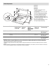
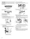
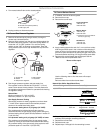
Large Dual Burner
A.Burner cap
B.Burner base
Medium Burner
A.Burner cap
B.Burner base
C.Choke (for use with medium
burner, LP gas only)
Small Burner
A.Burner cap
B.Burner base
Burner orifice spud
A. Size stamp or color
A
B
A
B
C
A
B
A
Burner
Rating
Color Size Burner Style
3,000 BTU Blue 0.55 mm Small burners
11,100 BTU Yellow 0.97 mm Medium burners
14,000 BTU Red/
Green
Green
1.05mm
0.35 mm
Large burner - main
Large burner - simmer