


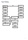
11
FO 0199
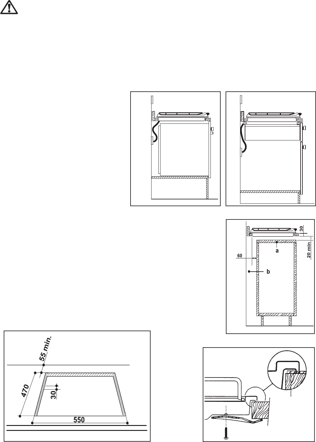
a
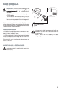
Seal
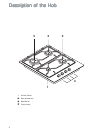
Dimensions are given in mm
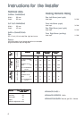
Building InBuilding In
Building InBuilding In
Building In
BB
BB
B
uilding ouilding o
uilding ouilding o
uilding o
vv
vv
v
er a cupboarer a cupboar
er a cupboarer a cupboar
er a cupboar
d ord or
d ord or
d or
dradra
dradra
dra
ww
ww
w
erer
erer
er
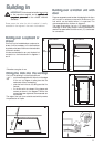
If the hob is to be installed above a cupboard or
drawer it will be necessary to fit a heat resistant
board below the base of the hob on the underside
of the work surface.
It is also recommended to carry out the electrical
connection to the hob as shown in diagrams 1
and 2.
ON/OFF SWITCH
FLEX
OUTLET
ON/OFF SWITCH
FLEX
OUTLET
FO 2563
FO
2564
FO 2044
11
11
1
22
22
2
33
33
3
Fitting the Hob into the wFitting the Hob into the w
Fitting the Hob into the wFitting the Hob into the w
Fitting the Hob into the w
orktoporktop
orktoporktop
orktop
Carry out the building in of the hob as follows:
• put the seals supplied with the hob, on the edges
of the cut out diagram 4, taking care that the
seals meet without overlapping;
• place the hob in the cut out, taking care that it is
centred;
• fix the hob with the relevant fixing clamps and
screws, as shown in the diagram 5. When the
screws have been tightened, the excess seal can
be removed.
The edge of the hob forms a double seal which prevents
the penetration of liquids.
IMPORTANTIMPORTANT
IMPORTANTIMPORTANT
IMPORTANT
::
::
:
This hob must be installed acccording
to the instruction supplied, and by
qualified andqualified and
qualified andqualified and
qualified and
competent personnelcompetent personnel
competent personnelcompetent personnel
competent personnel to the relevant National
Standards.
BB
BB
B
uilding ouilding o
uilding ouilding o
uilding o
vv
vv
v
er a kitchen unit wither a kitchen unit with
er a kitchen unit wither a kitchen unit with
er a kitchen unit with
doordoor
doordoor
door
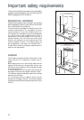
Proper arrangements must be taken in designing the furniture
unit, in order to avoid any contact with the bottom of the
hob which can be heated when it is operated. The
recommended solution is shown in diagram 3.
The panel fitted under the hob ("a") should be easily
removable to allow easy access if technical assistance is
needed. The space behind the kitchen unit ("b") can be used
for connections.
Please ensure that when the hob is installed it is easily
accessible for the engineer in the event of a breakdown.
55
55
5
44
44
4
FO 2098FO 2098
FO 2098FO 2098
FO 2098