


INSTALLATION STEPS
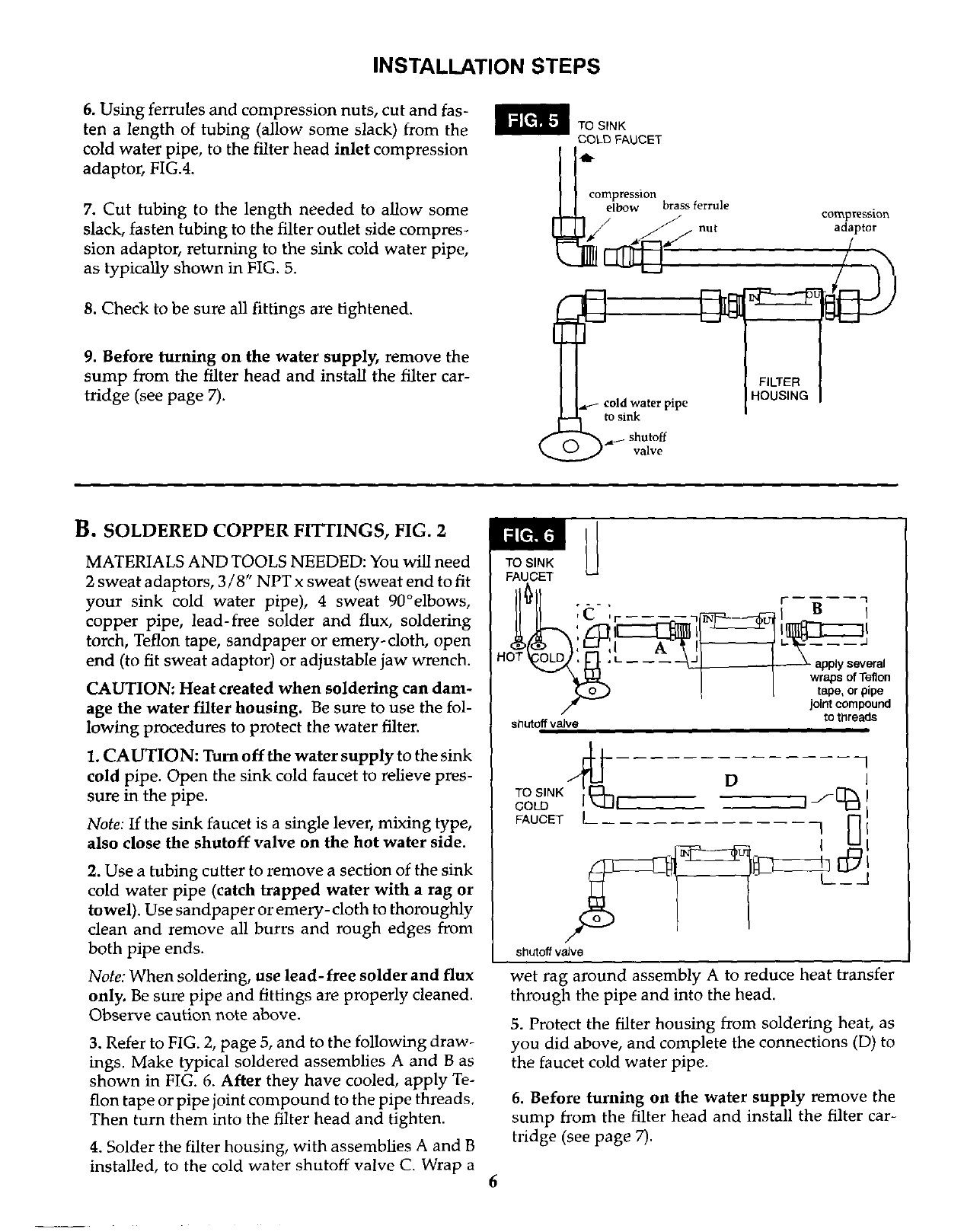
6. Using ferrules and compression nuts, cut and fas-
ten a length of tubing (allow some slack) from the
cold water pipe, to the filter head inlet compression
adaptor, FIG.4.
7. Cut tubing to the length needed to allow some
slack, fasten tubing to the filter outlet side compres-
sion adaptor, returning to the sink cold water pipe,
as typically shown in FIG. 5.
8. Check to be sure all fittings are tightened.
9. Before turning on the water supply, remove the
sump from the filter head and install the filter car-
tridge (see page 7).
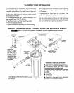
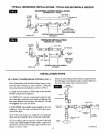
TO SINK
COLD FAUCET
compression
elbow brass ferrule
/ cold water pipe
to sink
_.a_- shutoff
J valve
FILTER
HOUSING
compression
adaptor
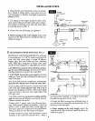
B. SOLDERED COPPER FITTINGS, FIG. 2
MATERIALS AND TOOLS NEEDED: You will need
2 sweat adaptors, 3 / 8" NPT x sweat (sweat end to fit
your sink cold water pipe), 4 sweat 90°elbows,
copper pipe, lead-free solder and flux, soldering
torch, Teflon tape, sandpaper or emery-cloth, open
end (to fit sweat adaptor) or adjustable jaw wrench.
CAUTION: Heat created when soldering can dam-
age the water filter housing. Be sure to use the fol-
lowing procedures to protect the water filter.
1. CAUTION: Turn offthe water supply to the sink
cold pipe. Open the sink cold faucet to relieve pres-
sure in the pipe.
Note: If the sink faucet is a single lever, mixing type,
also close the shutoff valve on the hot water side.
2. Use a tubing cutter to remove a section of the sink
cold water pipe (catch trapped water with a rag or
towel). Use sandpaper or emery- cloth to thoroughly
dean and remove all burrs and rough edges from
both pipe ends.
Note: When soldering, use lead-free solder and flux
only. Be sure pipe and fittings are properly cleaned.
Observe caution note above.
3. Refer to FIG. 2, page 5, and to the following draw-
ings. Make typical soldered assemblies A and B as
shown in FIG. 6. After they have cooled, apply Te-
flon tape or pipe joint compound to the pipe threads.
Then turn them into the filter head and tighten.
4. Solder the filter housing, with assemblies A and B
installed, to the cold water shutoff valve C. Wrap a
TO SINK
FAUGET
I_ .- _ I" B 1
II II ,C 'r .... lr_-----_al I
I I I
.OT -; pl era,
I I wrapsofT?tlon
I t tape, or pipe
/" joint compound
shutoff valve to threads
TO SINK
COLO I
FAUCET l
Y
shutoff valve
1
D I
I_ L__J
wet rag around assembly A to reduce heat transfer
through the pipe and into the head.
5. Protect the filter housing from soldering heat, as
you did above, and complete the connections (D) to
the faucet cold water pipe.
6. Before turning on the water supply remove the
sump from the filter head and install the filter car-
tridge (see page 7).
6