


STEP 8
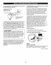
Adjusting the Air Adjustment Shutter
if Necessary
To determine if the oven burner flames are burning
properly, first remove the oven bottom_
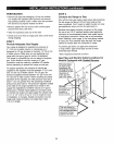
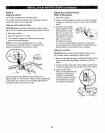
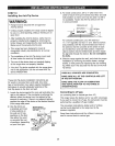
To remove the oven bottom:
1. Remove the knurled
screws holding down
the rear of the oven
bottom
2. Grasp the oven
bottom at the finger
slots on each side..
3. Lift the rear of the
oven bottom enough
Oven bo_om
to clear the lip of the range frame, push it back, and
then pull it up and out.
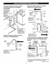
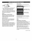
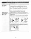
With the oven bottom
removed, properly c
adjusted flames should _"
have approximately I"
(2.5 cm) blue cones
and, if range is supplied
with natural gas, should
burn with no yellow
tipping. (With most LP "_'_
gas, small yellow tips at the end of outer cones are
normaL) Flames should not lift off the burner ports.
If lifting is observed, gradually reduce air shutter
opening until flames are stabilized.
The shutter for the oven burner is near the back wall of
the oven and behind the broiler drawer1.To remove the
broiler drawer:
1.. Pull the drawer out until it stops, then push it back in
about 1" (2.5 cm)..
2. Grasp the handle, lift and pull the broiler drawer out.
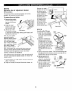
Remove the metal
shield at the rear of
the drawer cavity.
The air adjustment
shutter is behind
this shield.. To adjust
the flow of air to
the burner, loosen
the Phillips-head
screw and rotate
the shutter to allow
more or less air
into the burner tube.
Loosen
adjustmentshutter
Metal shield
STEP 9
Leveling the Range
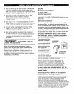
1. Install the oven shelves
in the oven, then position
the range where it will be
installed
2. Check for levelness by
placing a spirit levei or a
partially filled cup of water
on one of the oven shelves.
If using a spirit level, take
two readings--with the level
placed diagonally first in
one direction and then the
other.
Raise
range
t ower
range
(on some models)
3_ Remove the broiler drawer. The front leveling legs can
be adjusted from the bottom and the rear legs can be
adjusted from the top or the bottom.
4. Use an open-end or
adjustable wrench to
adjust the leveling legs
until the range is level.
5. After the range is level,
slide the range away
from the walt so that the
Anti-Tip device can be
installed.
t ml ii _, wer
(on some models)
38