


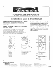

CHECK INSTALLATION DIMENSIONS
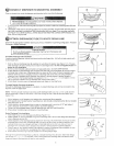
A. Disposer Height
B. Distance from bottom of sink
bowl to centerline of discharge
outlet. (Add 1/2" when stainless
steel sink is used.) A,
C: Distance from centerline of
L
the discharge outlet to end
of discharge tube.
D: D_sposer Width
E: Distance from disposer vertical
centerline to centerline of
P-trap connection.
] B
D ---'------
F: Centerline of disposer discharge to centerline at waste pipe entering wall.
(Dimension "F" must be greater than 1/4" to prevent standing water in disposer.)
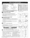
If replacing an existing disposer, skip ahead to Instruction 6. ]
If this is a first time installation, continue with Instruction 2.
/
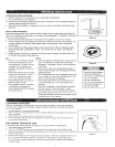
DISCONNECT SINK DRAIN
1. Loosen nut (A) at top of "P-trap" with pipe wrench (see Figure 2-1).
2. Loosen nut (B) at top of extension pipe. Remove extension pipe.
3. Loosen nut (C) at base of sink flange. (If nut is corroded or too tight, apply
penetrating lubricant
4. Push s_nk flange up through sink hole and remove it (see Figure 2-2).
5. Clean sink flange area of any putty or other debris.
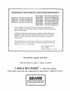
DISASSEMBLE NEW DISPOSER
MOUNTING ASSEMBLY
1. Insert wrenchette (or screwdriver) into one mounting lug and hold lower mount-
ing ring securely with one hand (see Figure 3-1). With your other hand, turn
mounting assembly counterclockwise to remove mounting assembly from lower
mounting ring
2. Turn mounting assembly over (see Figure 3-2) and loosen three mounting
screws (A) until you can access snap ring (B).
3 Use screwdriver to pry snap ring off of sink flange. Mounting assembly will
now come apart.
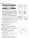
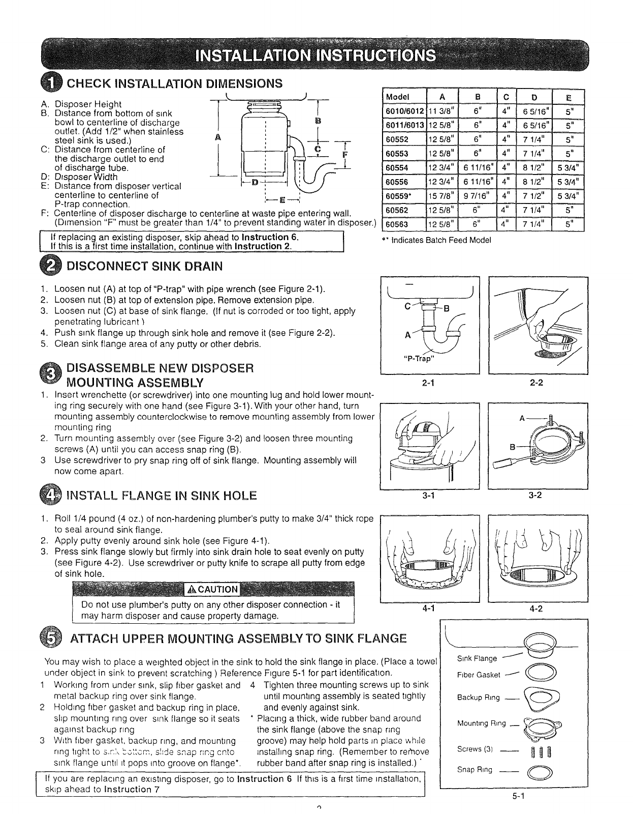
INSTALL FLANGE IN SINK HOLE
1odel A B C b E
010/6012 113/8" 6" 4" 6 5/16" 5"
01116013 12 5/8" 6" 4" 6 5/16" 5"
0552 12 5/8" 6" 4" 7 1/4" 5"
5/8'--6,' 4,' 71/4,' 5"
_3/4" 611/16" 4'=.__ 81/2'.=_=___'53/4'_
3/4" 6 11/16" 4" 8 1/2" 5 3/4"
0559* _1157/8" 9 7/16" 4" 7 1/2" 5 3/4"
-- " 6" 4" 7 1/4" 5"
6" 4" 7 1/4" 5"
_'"Indicates Batch Feed Model
J
" - r " /_
2-1 2-2
/ !i
3-1 3-2
1.
2.
3.
Roll 1/4 pound (4 oz.) of non-hardening plumber's putty to make 3/4" thick rope
to seal around sink flange.
Apply putty evenly around sink hole (see Figure 4-1).
Press sink flange slowly but firmly into sink drain hole to seat evenly on putty
(see Figure 4-2). Use screwdriver or putty knife to scrape all putty from edge
of sink hole.
_k CAUTION
Do not use plumber's putty on any other disposer connection - it
may harm disposer and cause property damage.
4-1 4-2
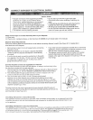
ATTACH UPPER MOUNTING ASSEMBLYTO SINK FLANGE
You may wish to place a we=ghted object in the sink to hold the sink flange in place. (Place a towel
under object in sink to prevent scratching ) Reference F=gure 5-1 for part identification.
1 Working from under sink, slip fiber gasket and
metal backup ring over sink flange.
2 Holding fiber gasket and backup ring in place,
shp mounhng nng over s_nkflange so it seats
against backup nng
3 W_th fiber gasket, backup nng, and mounting
ring hght to S,F.'.__ottom, shde snap r',ng cnto
s_nk flange until _tpops {nto groove on flange'.
4 Tighten three mounting screws up to sink
until mounting assembly is seated tightly
and evenly against sink.
* Placing a thick, wide rubber band around
the sink flange (above the snap ring
groove) may help hold parts Jnplace _,,hde
tnstalhng snap ring. (Remember to rer'nove
rubber band after snap ring is installed.) '
If you are replacing an existing disposer, go to Instruction 6 If this is a first time _nstallahon, 1
skip ahead Io Instruction 7
J
Sink Flange
Fiber Gasket /
Backup R=ng __ _._'_).
MountEng RLng __ X_-@
Snap Ring O
5-1