


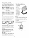
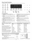

Before Setting Surface Controls
Check Burner Cap Placement Before Operating
the Surface Burners
To prevent flare-ups and avoid creation of harmful by-
products, do not use the cooktop without aii burner caps
property installed to insure proper ignition and gas flame size.
It is very important to be sure that aii surface burner caps
and burner grates are property installed and in the correct
locations BEFORE operating the cooktop burners.
Remember:
° Always keep surface burner caps in place whenever using
a surface burner.
° When placing the burner caps, be sure that all burner caps
are seated firmly and rest level on top of burner heads.
° For proper flow of gas and ignition of burners DO NOT
aflow spills, food, cleaning agents or any other material
to enter the gas orifice port opening.
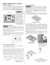
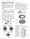
Round Style Burners
The burner cap lip (See Fig. 1) should fit snug into the center
of burner head and rest level. Refer to Figs. 2 & 3 for
correct and incorrect burner cap placement. Once in place,
you may check the fit by gently sliding the burner cap
from side to side (Fig. 4) to be sure it is centered and firmly
seated. When the burner cap lip makes contact inside the
center of the burner head you will be able to feel it. Please
note that the burner cap should NOT move off the center of
the burner head when sliding from side to side.
Burner Cap
Burner Head _ _ '_ Burner Cap Lip
Fig. 1
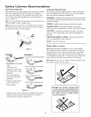
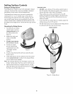
Double Ring Style Burners
The Double Ring burner only operates property with two
burner caps in place. Be sure the burner cap lips are
positioned facing down towards the burner head (Fig. 5)
and into the recessed areas (Fig. 6) on each side of the
burner head. Be sure both burner caps are seated firmly and
rest level on the burner head before operating.
Check the fit for each cap using the same method for the
round burner caps by gently sliding each cap from side to
side. Please note that the burner cap lips should NOT move
out of recessed areas of the burner head.
Burner Caps
Fig. 5
Recessed area
Burner Head
Correct Burner Cap Incorrect Burner Cap
Placement Placement
Fig. 2 _ Fig. 3
Fig. 4
10
Fig. 6
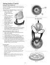
Bridge Style Burners
Install Burner Caps, these include one Bridge Burner Center
Cap (rectangular shaped) and the two Bridge Burner End
Caps (The Bridge
Burner End Caps will
fit either the front or
rear Bridge Burner Bridge
Head locations). Burner
Make sure that the End
lips located under Cap
the Bridge Burner
Caps fall into the Bridge
slots located in the Burner
Bridge Burner Head Center
(See arrows in Figure Cap
7) and that aii the
Bridge Burner Caps
lie flat and evenly
on the Bridge Burner
Head.
Bridge Burner Head
I
igniter
Hole
Bridge
Burner
End
Cap
Fig. 7
igniter
Hole