


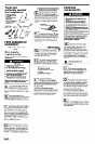
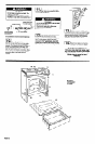
Tools and
materials needed
for installation:
l
gas line shutoff valve
l
L.P.-resistant pipe-joint
compound
l
A.G.A. design-certified
flexible metal
connector (4-5 feet)
l
2 flare union adapters for
connection to pressure
regulator (112” NPT x
112” or 314 ’ I.D.)
318” ratchet
screwdriver
Parts supplied for
installation:
m-+-Jem
4 screws
Gas supply
requirements
Observe all governing codes and
ordinances.
Fire Hazard
l
Range must be connected to a
regulated gas supply.
l
L.P. gas supply must Not exceed a
pressure of 14” water column. This
must be checked by a qualified
technician before installing the range.
l
Do Not use an open flame to test for
leaks from gas connections.
l
New, A.G.A.-design-certified, flexible
metal gas line connector should be
used when codes permit.
Failure to follow these instructions could
result in a fire, explosion or personal
injury.
El
This installation must conform with
.
local codes and ordinances. In the
absence of local codes, installations
must conform with American National Standard,
National Fuel Gas Code ANSI Z223.1- latest
edition.**
[B
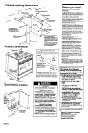
Input ratings shown on the
serial/rating plate are for elevations up
n to 2,000 feet. For elevations above
2,000 feet, ratings are reduced at a rate of 4%
for each 1,000 feet above sea level.
El
This range is equipped for use with
NATURAL gas. It is design-certified by
A.G.A. for NATURAL and L.P. gas
with appropriate conversion. The serial/rating
plate, located on the oven frame behind the
oven door, has information on the type of gas
that can be used. If this information does not
agree with the type of gas available, check with
your KitchenAid dealer. Conversion to L.P. gas
requires Kit No. 4175461, available from your
KitchenAid Dealer. This conversion must be
done by a qualified technician.
Provide a gas supply line of 3/4” rigid
pipe to the range location. A smaller
size pipe on long runs may result in
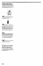
If local codes permit, a new A.G.A.
design-certified, 4-5 foot long, l/2” or
314” I.D., flexible metal appliance
connector is recommended for connecting this
range to the gas supply line. Do Not kink or
damage the flexible tubing when moving the
range. A l/2” male pipe thread is needed for
connection to pressure regulator female pipe
threads.
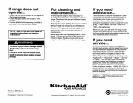
IF
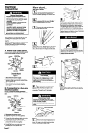
The supply line shall be equipped with
n
an approved shutoff valve. This valve
is for turning on or shutting off gas to
the appliance. This valve should be located in
the same room, but external to the range, and
should be in a location that allows ease of
opening and closing. Do Not block access to
shutoff valve.
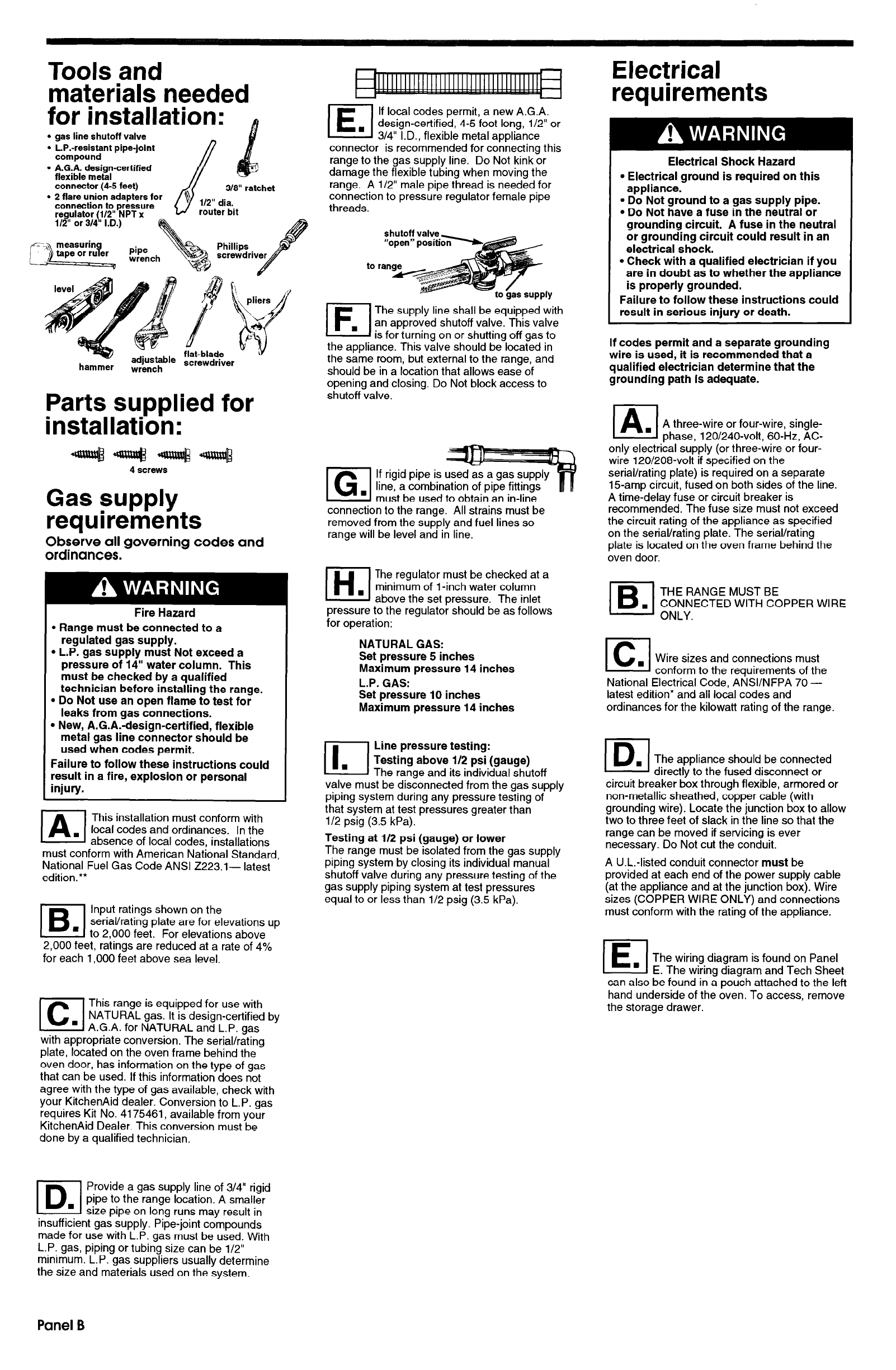
El
If rigid pipe is used
line, a combination of pipe fittings
must be used to obtain an in-line
connection to the range. All strains must be
removed from the supply and fuel lines so
range will be level and in line.
El
The regulator must be checked at a
minimum of 1 -inch water column
above the set oressure. The inlet
pressure to the regulator should be as follows
for operation:
NATURAL GAS:
Set pressure 5 inches
Maximum pressure 14 inches
L.P. GAS:
Set pressure 10 inches
Maximum pressure 14 inches
Line pressure testing:
Testing above i/2 psi (gauge)
The range and its individual shutoff
valve must be disconnected from the gas supply
piping system during any pressure testing of
that system at test pressures greater than
l/2 psig (3.5 kPa).
Testing at l/2 psi (gauge) or lower
The range must be isolated from the gas supply
piping system by closing its individual manual
shutoff valve during any pressure testing of the
gas supply piping system at test pressures
equal to or less than l/2 psig (3.5 kPa).
Electrical
requirements
Electrical Shock Hazard
l
Electrical ground is required on this
appliance.
l
Do Not ground to a gas supply pipe.
l
Do Not have a fuse in the neutral or
grounding circuit. A fuse in the neutral
or grounding circuit could result in an
electrical shock.
l
Check with a qualified electrician if you
are in doubt as to whether the appliance
is properly grounded.
Failure to follow these instructions could
result in serious injury or death.
If codes permit and a separate grounding
wire is used, it is recommended that a
qualified electrician determine that the
grounding path is adequate.
(A
. A three-wire or four-wire, single-
phase, 120/240-volt, 60-Hz, AC-
only electrical supply (or three-wire or four-
wire 120/208-volt if specified on the
serial/rating plate) is required on a separate
15-amp circuit, fused on both sides of the line.
A time-delay fuse or circuit breaker is
recommended. The fuse size must not exceed
the circuit rating of the appliance as specified
on the serial/rating plate. The serial/rating
plate is located on the oven frame behind the
oven door.
le
THE RANGE MUST BE
. CONNECTED WITH COPPER WIRE
ONLY.
B-l
. Wire sizes and connections must
conform to the requirements of the
National Electrical Code, ANSVNFPA 70 -
latest edition* and all local codes and
ordinances for the kilowatt rating of the range.
I
The appliance should be connected
directly to the fused disconnect or
circuit breaker box through flexible, armored or
non-metallic sheathed, copper cable (with
grounding wire). Locate the junction box to allow
two to three feet of slack in the line so that the
range can be moved if servicing is ever
necessary. Do Not cut the conduit.
A U.L.-listed conduit connector
must
be
provided at each end of the power supply cable
(at the appliance and at the junction box). Wire
sizes (COPPER WIRE ONLY) and connections
must conform with the rating of the appliance.
El
n
The wiring diagram is found on Panel
E. The wiring diagram and Tech Sheet
can also be found in a pouch attached to the left
hand underside of the oven. To access, remove
the storage drawer.
insufficient gas supply. Pipe-joint compounds
made for use with L.P. gas must be used. With
L.P. gas, piping or tubing size can be l/2”
minimum. L.P. gas suppliers usually determine
the size and materials used on the system.
Panel B