Electrical
requirements
Eleclrlcal Shock Hazard
* Eleclrical ground Is required on lhls
appliance.
- If cold waler pipe is inlerrupled by
plastic, non-metallic gaskets or other
insulating malerlals, Do Not use for
grounding.
- Do No1 ground lo a gas pipe.
- Do Nol have a fuse in the newel or
grounding circuit. A fuse in the neulral
or grounding circuit could result in an
electrical shock.
- Do Not use en extension cord with lhis
appliance.
-Check with a qualified electrician if you
are in doubt as to whether the appliance
is properly grounded.
Failure lo lollow lhese Instructions could
resull in serious iniutv or dealh.
I
II codes permit end e separate grounding
wire is used. II is recommended that a
qualilied eleclrlcian determine that the
grounding path Is adequate.
IMPORTANT:
Save lnslallelion Inslruclions lor the local
electrical Inspector’s use.
El
Thts appltance must be connected lo
’ the proper eleclncat vollage and
frequency spectfted on Ihe senatJraltnq plate
The serrallralrng plale rs located on the frame
behrnd the oven door
The branch circuit load lor a counler-mounted
coaklop and nol more than two wall-mounted
ovens, all supplred from a srngle branch crrcurt
and localed rn Ihe same room. shall be
compuled by addtng lhe nameplale ratmgs of
the rndrvrdual appliances and lrealtng lhrs tolal
as equivalent lo one range
A three-wrre or four-we. srngle phase,
1201240-voll. 60-t+ AC-onlv eleclrrcat suoolr
(or three-wee or lourwre, 120/205-volt II ’
specrfred on the nameplate) IS requrred on a
separate 30.ampere crrcu~t. fused on both srdes
01 the lkne A trme-delay fuse or crrcutt breaker
1s recommended
NOTE Wthng musl be modrfred lor 205.volt
usage See “Connectrng to 205volt crrcurt.”
Panel B
OVEN MUST BE CONNECTED
WITH COPPER WIRE ONLY.
ICI
II IS the personal responsrbrlrty and
’ obtrgatron 01 Ihe customer lo contact
a qualrhed electricran lo assure that the
electrical installation IS adequate and tn
conformance wrlh the Natronal Electrrcal Code,
ANSIINFPA 70.lalest edrtron.’ and all local
codes and ordmances for the krtowan ratrng of
the oven
Copres 01 the standards lksted may be
oblarned lrom
‘National Fire Protection Associslion
Ballerymarch Park
Quincy, Massachusells 02269
Thrs applrance should be connected
drrectly to the lused drsconnect or crrcult
breaker box through Ilexrble. armored or non-
metallfc sheathed, copper cable (wrth groundrng
wire) Allow two to three leet of slack rn the lkne
so that Ihe oven can be moved II servtcrng IS
ever necessary Do Nol cut lhe conduil.
A U L -Isled condurl connector rt?usl be
prowded at each end ot the power supply cable
(al the applrance and at the ]unclron box) Wires
s~zes (COPPER WIRE ONLY) and connectrons
must conlorm wrth Ihe ralrng of Ihe appliance
Connecting
lo 208~volt circuit
1 Remove access panel located on back ot
OW”
2. Loosen Ihe f,rst and second screws I” the
terminal block
3. Place metal jumper between Ihe llrsl and
second screws
4. Trghten screws
5. Replace access panel
Electrical
connection
Tt 11s appliance 1s manufaclured wrth whrte
(neulral) power supply wrre and a caBlnet-
connected green groundrng we twtsled together
Connecl Ihe appliance cable to the ~unclron box
through Ihe U L -16184 condull COnneClOr
Complete electrical connection according to local
codes and ordrnances
Electrical Shock Hazard
. Electrical ground is required on this
appliance.
-Do No1 connect lo the electrical supply
until appliance is permanently
grounded.
. Disconnect power lo the junclion box
before making the eleclricsl
connection.
-This appliance must be connecled lo a
grounded, metallic, permanent wiring
system. or a grounding connector
should be connected lo the grounding
terminal or wire lead on the appliance.
Failure lo do so could result in a ftre.
personal injury or eleclrical shock
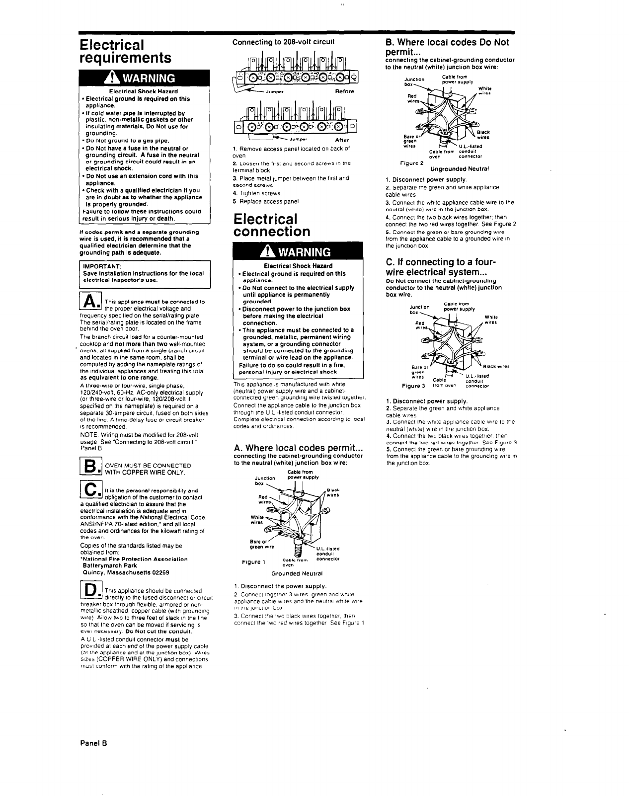
A. Where local codes permit...
connecting the cabinel-grounding conductor
to the neulral (white) junction box wire:
Grounded Neulral
1. Drsconnecl the power supply.
2. Connecl together 3 w,res green and while
appliance cable w,res and the neutra’ white ic~re
I” Ile ,uncmn box
3. Connect Ihe two black wres together then
connect the two red w,res logelher See Figure 1
B. Where local codes Do Not
permit...
connecting the cabinel-grounding conduclor
lo the neutral (while) junclton box wire:
Ungrounded Neutral
1. Disconnect power supply.
2. Separate Ihe green and whrte appliance
cable wires
3. Connect the whrte applrance cable ware to the
neutral twhrlel wre I” Ihe ,unctron box.
4. Connect the two black wares together. then
connect Ihe two red wares loaether See Fraure 2
5. Connect the green or bare groundrng we
from the applrance cable to a grounded we m
the )unctron box
C. If connecting to a four-
wire electrical system...
Do Nol connect the cabinel-grounding
conduclor lo the neulral (while) junction
box wire.
green
wtres
Figure 3
_. __._
1. Disconnect power supply.
2. Separate the green and whrte appliance
cable wires
3. Connect Ihe white appl~aw cable wre to the
neutral (white) we in Ihe junctron box
4. Connecl the two black wrres lagether lhen
connect the two red wes logelher See Figure 3
5. Connecl the green or bare groundrng we
from the appliance cable to the grounding we !n
the lunct!on box
Panel B


