


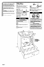
Tools needed for
installation:
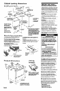
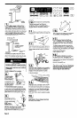
Power supply cord
Use a new 40-amp power supply cord.
Local codes may permit the use of a U.L.-listed,
250~volt, 40-ampere range power supply cord
(pigtail). Power supply cord should be Type SRD
or SRDT and be at least four feet long. The wires
that connect to the range must end with ring
terminals. A 3/4” (1.9 cm), U.L.-listed strain relief
must be installed where the power supply cord
connects to the range. (See Figures 1 and 2.)
Electrical
connections
NOTE:
The metal chassis of the range MUST be
earth-grounded in order for the control panel to work.
If the metal chassis of the range is not earth-
grounded, NO keypads will operate. Check with a
qualified electrician if you are in doubt as to whether
the metal chassis of range is earth-grounded.
flat-blade screwdriver
or-5116” (0.8 cm) nut
Where local codes permit connecting the
frame-grounding conductor to the neutral
(white) junction box wire:
This appliance is manufactured with the
neutral terminal connected to the cabinet. If
local codes Do Not permit connecting
cabinet-grounding conductor to neutral wire,
use “Four-wire connection” instructions.
ring
terminals
This blade connected
to this conduc
strain relief
(white or center)
Three-wire power supply cord
NEMA lo-50P
Figure 1
Electrical Shock/Fire Hazard
Check that wiring you are using matches
colors shown in illustrations and specified
in instruction steps. If wiring does Not
match, it is your responsibility to have a
qualified electrician install correct wiring.
Failure to follow these instructions could
result in fire, electrical shock or death.
hand or electric drill wood
floor: l/8” (0.3 cm) drill bit
concrete/ceramic floor:
3/16” (0.48 cm) carbide-
tipped masonry drill bit
314” 1.9 cm)
I U.L.- isted
strain relief
\.
NEUTRAL
(white)
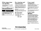
Parts supplied for
installation:
grounding prong
Four-wire power supply cord
(Mobile home or other four-wire
installations)
NEMA lo-5OP
Figure 2
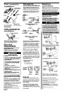
The power supply cord must have three No.-10
copper wires to match a three-wire receptacle of
NEMA Type 1 O-50R. (See Figure 3.)
For mobile home or other four-wire installations:
This appliance is manufactured with ground
connected to cabinet.
The ground must be
revised
so the green grounding wire of the four-
wire power cord is connected to the cabinet. See
four-wire electrical connection section, Panels C
and D.
When a four-wire receptacle of NEMA Type
14-50R is used (See Figure 4.), a matching
U.L.-listed, four-wire, 250~volt, 40-ampere, range
power supply cord (pigtail) must be used. This
cord contains four copper conductors with ring
terminals on the appliance end, terminating in a
NEMA Type 14-50P plug on the supply end. The
fourth (grounding) conductor must be identified
by a green or green/yellow cover and the neutral
conductor by a white cover. Cord should be Type
SRD or SRDT with a U.L.-listed strain relief and
be at least four feet long.
The
MINIMUM
conductor sizes for the copper
4-wire power supply cord are:
(Bracket must be securely mounted to sub-
floor. Thickness of flooring may require longer
screws to anchor the bracket to sub-floor.)
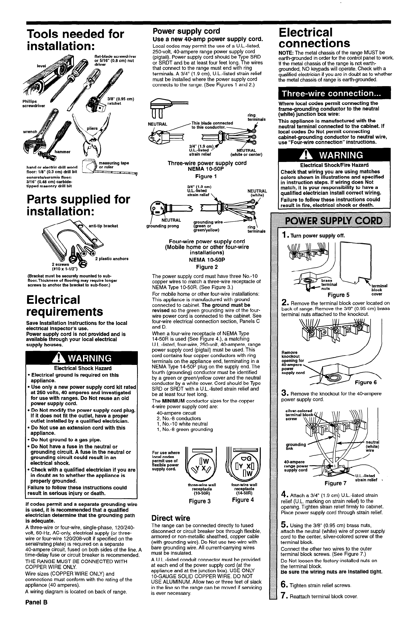
Figure 5
cover
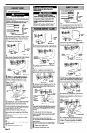
2.
Remove the terminal block cover located on
back of range. Remove the 3/8” (0.95 cm) brass
terminal nuts attached to the knockout.
Electrical
requirements
Save Installation Instructions for the local
electrical inspector’s use.
Power supply cord is not provided and is
available through your local electrical
supply houses.
Electrical Shock Hazard
l
Electrical ground is required on this
appliance.
. Use only a new power supply cord kit ratec
at 250 volts, 40 amperes and investigated
for use with ranges. Do Not reuse an old
power supply cord.
l
Do Not modify the power supply cord plug
If it does not fit the outlet, have a proper
outlet installed by a qualified electrician.
l
Do Not use an extension cord with this
appliance.
l
Do Not ground to a gas pipe.
l
Do Not have a fuse in the neutral or
grounding circuit. A fuse in the neutral or
grounding circuit could result in an
electrical shock.
l
Check with a qualified electrician if you arc
in doubt as to whether the appliance is
properly grounded.
Failure to follow these instructions could
result in serious injury or death.
3.
Remove the knockout for the 40-ampere
power supply cord.
silver-colored
’ ’
\\\\\\ 1
40-ampere circuit
2, No.-8 conductors
1, No.-1 0 white neutral
1, No.-8 green grounding
For use where
local codes
P
ermit use of
lexible power
supply cord.
P
1
UG
3
ny$l
-
n U.L.-listed ’
Figure 7
strain relief i
three-wire wall
receptacle
(16SOR)
four-wire wall
receptacle
(14~SOR)
Attach a 314” (1.9 cm) U.L.-listed strain
on strain relief) to the
rain relief firmly to cabinet.
Place power supply cord through strain relief.
Using the 3/8” (0.95 cm) brass nuts,
ch the neutral (white) wire of power supply
to the center, silver-colored screw of the
her two wires to the outer
rews. (See Figure 7.)
e factory-installed nuts on
g nuts are installed tight.
Figure 3
Figure 4
If codes permit and a separate grounding wire
is used, it is recommended that a qualified
electrician determine that the grounding path
is adequate.
A three-wire or four-wire, single-phase, 120/240-
volt, 60-Hz, AC-only, electrical supply (or three-
wire or four-wire 120/208-volt if specified on the
serial/rating plate) is required on a separate
40-ampere circuit, fused on both sides of the line. A
time-delay fuse or circuit breaker is recommended.
THE RANGE MUST BE CONNECTED WITH
COPPER WIRE ONLY.
Wire sizes (COPPER WIRE ONLY) and
connections must conform with the rating of the
appliance (40 amperes).
A wiring diagram is located on back of range.
Panel B
Direct wire
The range can be connected directly to fused
disconnect or circuit breaker box through flexible,
armored or non-metallic sheathed, copper cable
(with grounding wire). Do Not use two-wire with
bare grounding wire. All current-carrying wires
must be insulated.
A U.L.-listed conduit connector must be provided
at each end of the power supply cord (at the
appliance and at the junction box). USE ONLY
lo-GAUGE SOLID COPPER WIRE. DO NOT
USE ALUMINUM. Allow two or three feet of slack
in the line so the range can be moved if servicing
is ever necessary.
6.
Tighten strain relief screws
.-:-..: :..
Iv
:::.::.:::.
..-.-.-.-.
. Reattach terminal block cover.