


c
0
1
l - 0
Mobile home or other four-wire
installations:
..,,,..-..:
:;xr::;ig
:;j:$~$;
. ..-.-.-.-.
:::‘“:
..::::-..
. ..-...-...
. . . . . . . . . -..
. ..- _.......
. . . . . . . . . . . .
..:..::..
. . . . . _.....
:;:;:::;:::i
. . . . . . . . . .
i:;:;:;:;:;:
Electrical Shock/Fire Hazard
_...........
. . . . . . . . . . . .
:;:/:/:j:j:j
:.. . . . . . ,.,,
I’
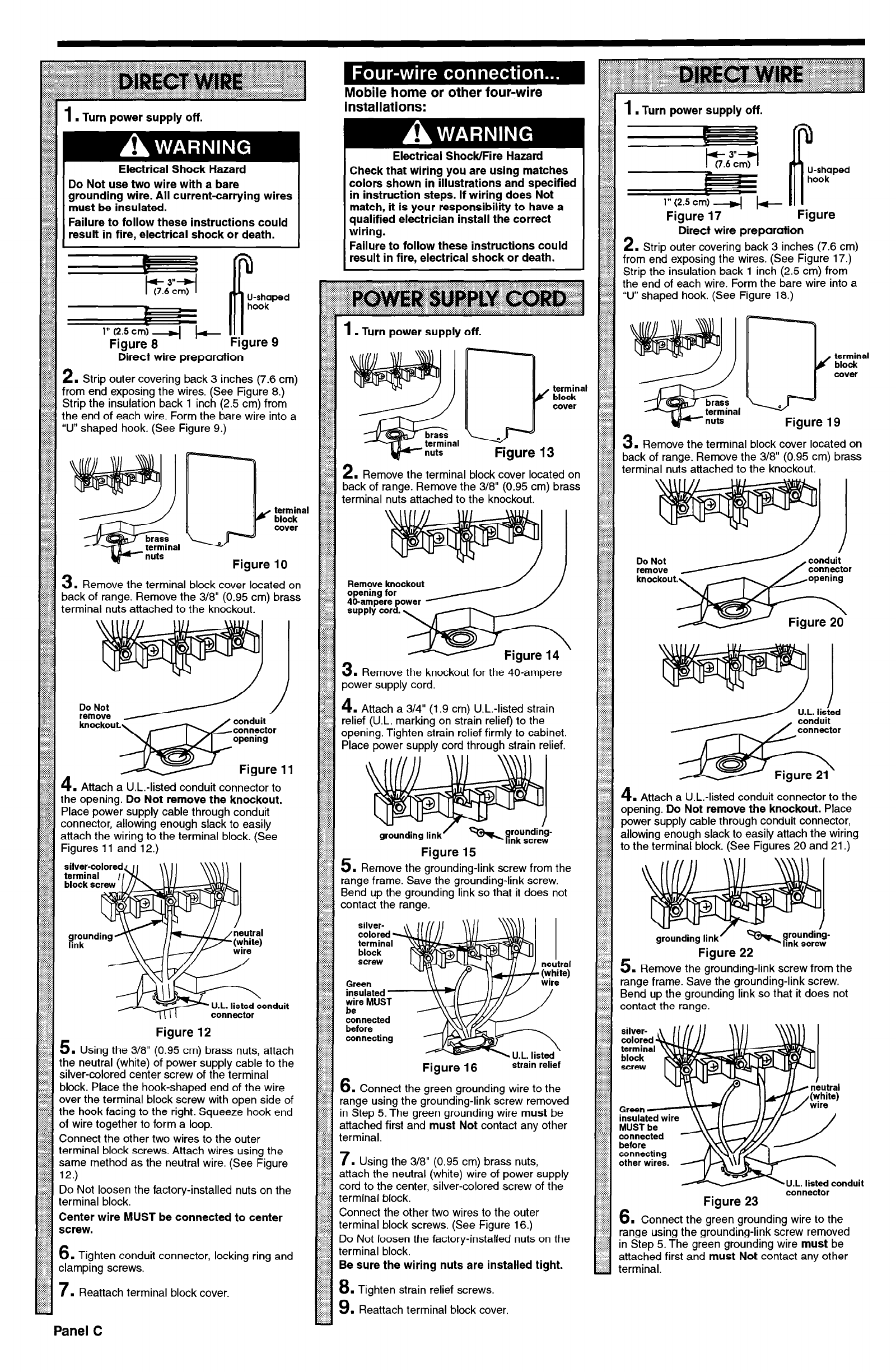
. Turn power supply off.
1.
Turn power supply off.
7-
3”
(7.6 cm)
R
U-shaped
hook
Check that wiring you are using matches
colors shown in illustrations and specified
in instruction steps. If wiring does Not
match, it is your responsibility to have a
qualified electrician install the correct
wiring.
Failure to follow these instructions could
result in fire, electrical shock or death.
Electrical Shock Hazard
Do Not use two wire with a bare
grounding wire. All current-carrying wires
must be insulated.
Failure to follow these instructions could
result in fire, electrical shock or death.
I
Figure 17 ’ ’
Figure
jjjj;j;j;jjj
::::::::::::
. . . . . . . . . . . .
. . . . . . . . . . ,.
Direct wire preparation
;<;;j;g
:,:,:,:.:.:.
::::::::::::
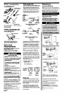
2. Strip outer covering back 3 inches (7.6 cm)
$33 from end exposing the wires. (See Figure 17.)
$$$ Strip the insulation back 1 inch
(2.5
cm) from
the end of each wire. Form the bare wire into a
“U” .&aped hook. (See Figure 18.)
.
terminal
II I hook’
Figure 9
:::::::::::
:i:i:;:;:>
l&zl
:;:;:i:{::
:.:-:...-.
: :>>:::
1
. Turn power supply off.
Direct wire preparation
2. Strip outer covering back 3 inches (7.6 cm)
from end exposing the wires. (See Figure 8.)
Strip the insulation back 1 inch (2.5 cm) from
the end of each wire. Form the bare wire into a
“U” shaped hook. (See Figure 9.)
v block
J
cover
Figure 13
3.
Remove the terminal block cover located on
back of range. Remove the 318” (0.95 cm) brass
terminal nuts attached to the knockout.
g/g
2
II
. Remove the terminal block cover located on
$2 back of range. Remove the 3/8” (0.95 cm) brass
~$$$ terminal nuts attached to the knockout.
terminal
4f block
Do Not
E:E”t.;r
the terminal block cover located on
of range. Remove the 3/8” (0.95 cm) brass
nuts attached to the knockout.
Remove knockout
. Remove the knockout for the 40-ampere
power supply cord.
.:y:::::::
4.
Attach a 3/4” (1.9 cm) U.L.-listed strain
$3; relief (U.L. marking on strain relief) to the
$$$; opening. Tighten strain relief firmly to cabinet.
@ Place power supply cord through strain relief.
:::::::::::
:::::::::::
:::::::::::
:::::::::::
:::::::::::
;$;j;$;
i$$i;;;i
:::::::::::
jjjjjjjjj{j
:::::::::::
~~~~~~~~~~~
::::::::y
:::::::::::
:::::::::::
::::::I:::;
::::::,:.:.
ilyiyy$
::‘::fi:::
4.
Attach a U.L.-listed conduit connector to the
opening.
Do Not remove the knockout.
Place
power supply cable through conduit connector,
allowing enough slack to easily attach the wiring
to the terminal block. (See Figures 20 and 21.)
4.
Attach a U.L.-listed conduit connector to
the opening.
Do Not remove the knockout.
Place power supply cable through conduit
connector, allowing enough slack to easily
attach the wiring to the terminal block. (See
Figures 11 and 12.)
silver-coloredc 11
\\ II \\\\I\ I
Figure 15
$$; 3.R
II
$$$i
emove the grounding-link screw from the
range frame. Save the grounding-link screw.
$$$ Bend up the grounding link so that it does not
contact the range.
block screw
1 // \
silver-
colored
terminal
block
grounding link
r
Figure 22
/
aondui t
screw
3. Remove the grounding-link screw from the
range frame. Save the grounding-link screw.
Bend up the grounding link so that it does not
contact the range.
Green
insulated -
wire MUST
be
connected
before
connecting
Figure 12
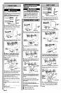
5. Using the 3/8” (0.95 cm) brass nuts, attach
the neutral (white) of power supply cable to the
silver-colored center screw of the terminal
block. Place the hook-shaped end of the wire
over the terminal block screw with open side of
the hook facing to the right. Squeeze hook end
of wire together to form a loop.
Connect the other two wires to the outer
terminal block screws. Attach wires using the
same method as the neutral wire. (See Figure
12.)
Do Not loosen the factory-installed nuts on the
terminal block.
Center wire MUST be connected to center
screw.
6.
Tighten conduit connector, locking ring and
clamping screws.
7
. Reattach terminal block cover.
silver-
colored
terminal
block
screw
Figure 16
strain relief
6.
Connect the green grounding wire to the
range using
the
grounding-link
screw removed
in Step 5. The green grounding wire must be
attached first and must Not contact any other
(0.95 cm) brass nuts,
(white) wire of power supply
cord to the center, silver-colored screw of the
Connect the other two wires to the outer
screws. (See Figure 16.)
factory-installed nuts on the
Be sure the wiring nuts are installed tight.
relief screws.
Reattach terminal block cover.
other wires. -
Jxonduit
Figure 23
connector
Connect the green grounding wire to the
range using the grounding-link screw removed
in Step 5. The green grounding wire
must
be
attached first and
must Not
contact any other
terminal.
Panel C